
Movement analysis display apparatus and movement analyzing method

a technology of movement analysis and display apparatus, which is applied in the direction of apparatus for force/torque/work measurement, gymnastic exercise, instruments, etc., can solve the problems of increasing the size of the apparatus, taking time to analyze data, and insufficiently determining the poor movement of fingers

Active Publication Date: 2011-02-22
HITACHI LTD
View PDF6 Cites 2 Cited by
  • Summary
  • Abstract
  • Description
  • Claims
  • Application Information

AI Technical Summary

Benefits of technology

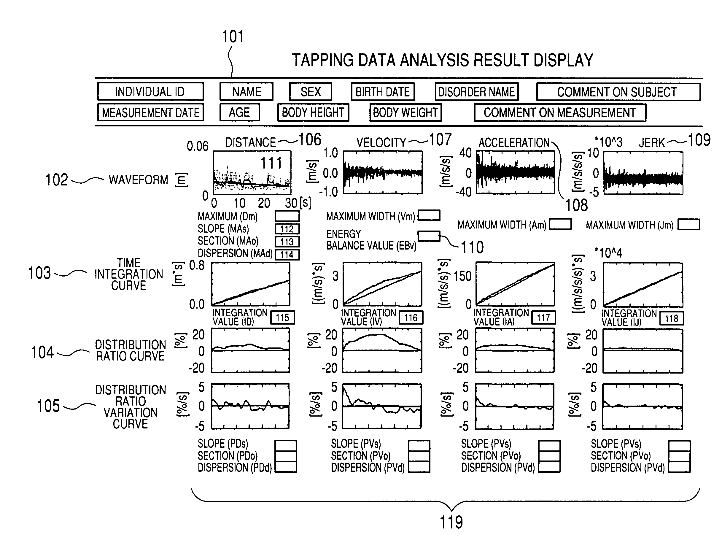
The present invention provides a movement analysis display apparatus that can quantitatively evaluate the movement information of a person regardless of the type of movement sensor used. The apparatus can analyze the waveform data of a movement sensor and display it on a screen in a quantitative manner. This allows for the evaluation of the movement of a person with Parkinson's disease, for example, by comparing their movement with a healthy person. The apparatus can also generate a distance waveform and evaluate the energy balance value to determine the state of "deadlock" or the attainment energy of the person. The apparatus can be used for research and diagnosis of brain disorders such as Parkinson's disease.

Problems solved by technology

36 to 47), there can be acquired nothing other than digital information of on / off with respect to the movement of fingers, thereby making it impossible to sufficiently determine the poorness of the movement of fingers which is the specific symptom of the Parkinson's disease.
665 to 676), there arises such problems that the apparatus is increased in size, and it takes time to analyze data.

Method used


Image

  • Movement analysis display apparatus and movement analyzing method
  • Movement analysis display apparatus and movement analyzing method
  • Movement analysis display apparatus and movement analyzing method

Examples


first embodiment

[0051]A first embodiment will be described. In the first embodiment, a movement is analyzed on the basis of a movement energy.

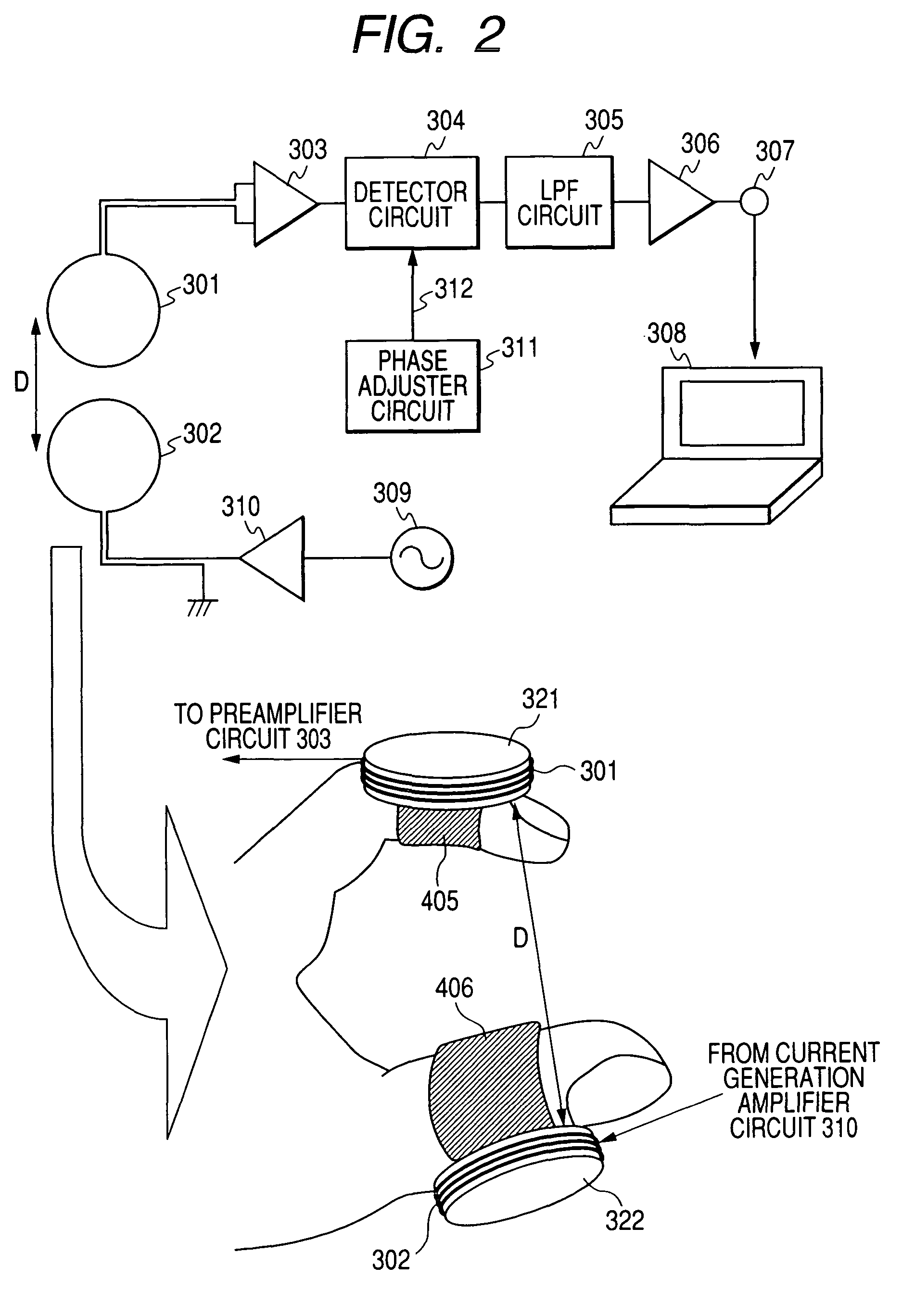
[0052]FIG. 1 is a block diagram showing the entire structure of a movement analysis display apparatus according to a first embodiment. As shown in FIG. 1, a movement analysis display apparatus 1 includes an information processing section 2, a movement sensor interface 3, display means 4, and input means 5.

[0053]A movement sensor 6 that acquires the movement information of a subject as waveform data is connected to the movement analysis display apparatus 1 through a movement sensor interface 3.

[0054]In this example, the “subject” is an object to be measured by the movement sensor 6 which moves such as a machine, an animal, or a human.

[0055]Then, in this embodiment, it is assumed that the subject is a Parkinson's patient so far as there is no specific description.

[0056]The movement sensor 6 detects the movement information of the subject in time series, and acq...

second embodiment

[0123]Now, a description will be given of a movement analysis display apparatus according to a second embodiment with reference to the drawings.

[0124]In the second embodiment, a movement is analyzed on the basis of an envelope curve generated in the distance waveform.

[0125]The second embodiment has a characteristic structure in an analysis processing section 21 within the information processing section 2. Accordingly, in the description of the second embodiment, partially the analysis processing section 21 will be described in more detail, but the duplicated description of the first embodiment will be omitted.

[0126](Analysis Processing Section)

[0127]FIG. 9 is a block diagram showing the structure of the analysis processing section 21 according to the second embodiment.

[0128]In this embodiment, the analysis processing section 21 according to the second embodiment includes movement waveform generating means 211, measurement data DB 212, and envelope curve generating means 214.

[0129][E...

third embodiment

[0166]Subsequently, a description will be given of a movement analysis display apparatus according to a third embodiment with reference to the drawings.

[0167]In the third embodiment, a movement is analyzed on the basis of movement information that has been integrated with respect to time.

[0168]The third embodiment has the characteristic structure in the analysis processing section 21 within the information processing section 2 as compared with the first embodiment. Accordingly, in the description of the third embodiment, particularly, the analysis processing section 21 will be described in detail, but the duplicated description of the first embodiment will be omitted.

[0169](Analysis Processing Section)

[0170]FIG. 15 is a block diagram showing the structure of the analysis processing section 21 according to the third embodiment.

[0171]In this example, the analysis processing section 21 according to the third embodiment includes movement waveform generating means 211, measurement data D...


PUM

PropertyMeasurementUnit
frequencyaaaaaaaaaa
movementaaaaaaaaaa
timeaaaaaaaaaa

Abstract

A movement analysis display apparatus includes a analyzing unit for analyzing waveform data of a time series which is acquired from a movement sensor, and a display unit for displaying an analysis result that is analyzed by the analyzing unit. The analyzing unit includes a movement waveform generating section for generating a movement waveform from the waveform data, an energy balance value calculating means for calculating a movement energy ratio in opposed movement directions in a velocity waveform, an envelope curve generating section for generating an envelope curve at a given time width in a distance waveform, and a time integration curve analyzing section for integrating a movement waveform with respect to time.

Description

CLAIM OF PRIORITY[0001]The present application claims priority from Japanese application JP 2005-120584 filed on Apr. 19, 2005, the content of which is hereby incorporated by reference into this application.BACKGROUND OF THE INVENTION[0002]The present invention relates to an apparatus for displaying movement information, and more particularly to an apparatus that analyzes a movement waveform that is acquired by a movement sensor, and displays quantitative movement information.[0003]The Parkinson's disease is an incurable disease that a lesion develops in a substantial nigra or striate body within brains which control a movement, and causes ataxia of involuntary movement such as walking. Also, since it is a progressive disease, when the Parkinson's disease is untreated for about ten years, they say that a patient becomes bedridden. Thus, early diagnostic and treatment have been demanded.[0004]However, the Parkinson's disease cannot be diagnosed by a blood test or diagnostic imaging r...

Claims


Application Information

Patent Timeline
Patent Type & Authority Patents(United States)
IPC IPC(8): A61B5/103A63B21/00A63B23/16G01L3/24G01L5/00A61B5/117A61B5/22A61B1/24A61B5/11
CPCA61B5/1124A61B5/1126A61B5/7242A61B5/6838A61B5/6826A61B5/1102A61B5/4082A61B2562/0219A61B5/7239
Inventor KANDORI, AKIHIKOMIYASHITA, TSUYOSHIOGATA, KUNIOMI
Owner HITACHI LTD
Learn More