
Bicycle frame with articulating linkage mounting arrangement

a technology of articulating linkage and frame, which is applied in the direction of friction roller based transmission, steering device, cycle equipment, etc., can solve the problems of affecting the design of the rest of the frame assembly, affecting the relative rotation of the axle and the and limiting the design of the remainder of the frame assembly. , to achieve the effect of preventing the relative rotation between the axle and the wheel support portion of the bicycl

Active Publication Date: 2011-02-22
SPECIALIZED BICYCLE COMPONENTS INC
View PDF16 Cites 29 Cited by
  • Summary
  • Abstract
  • Description
  • Claims
  • Application Information

AI Technical Summary

Benefits of technology

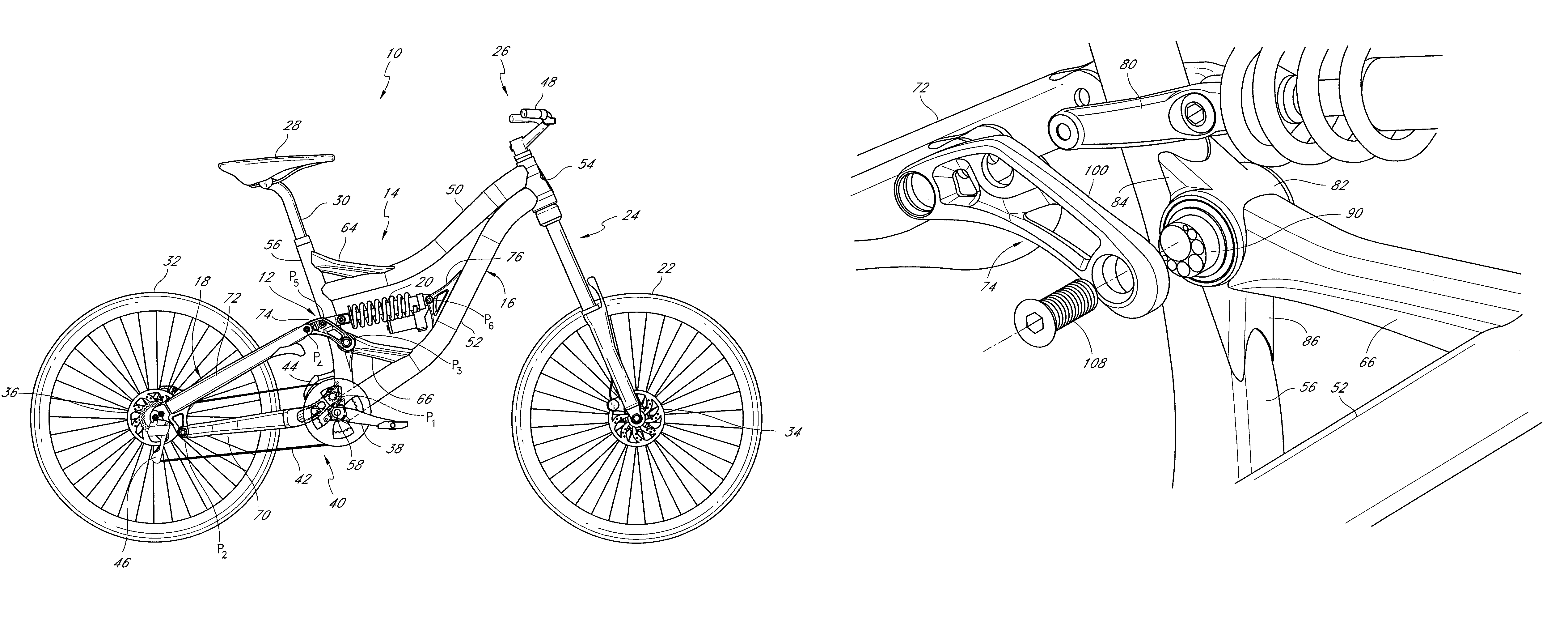
[0006]One or more embodiments of the present articulating linkage mounting arrangement fixedly couple one or more lever arms to a rotatable axle in a manner that is cost-effective to manufacture and the may overcome one or more of the drawbacks of the prior art designs described above. A preferred embodiment may include a lever arm that is fixedly coupled to an axle by a fastener having a fastener axis that is eccentric to, or offset from, the axis of rotation of the axle. Accordingly, relative rotation of the lever arm and axle is prevented such that the axle and lever arm rotate together as a unit.
[0010]A preferred embodiment involves an assembly including a bicycle wheel having a hub. The hub defines an opening defining an axis of rotation. An axle is positioned within the hub and supports the hub for rotation about the axis of rotation. The axle is coupled to a wheel support portion of a bicycle at a first end by a first fastener, which defines a first fastener axis that is offset from the axis of rotation. The axle is coupled to the wheel support portion of the bicycle at a second end by a second fastener, which defines a second fastener axis that is offset from the axis of rotation. Accordingly, relative rotation between the axle and the wheel support portion of the bicycle is prevented. The axle may be a front or rear wheel axle and the wheel support portion may be a front fork assembly or a frame of the bicycle.

Problems solved by technology

However, a disadvantage of such an arrangement is that a clearance space must be provided to accommodate the crossbar portion throughout the range of movement of the link during articulation of the sub-frame.
Such an arrangement can place limitations on the design of the remainder of the frame assembly.
However, with such an arrangement, the clamp force is not evenly distributed around the circumference of the axle.
Moreover, it may be difficult to provide enough retention force to prevent relative rotation between the lever arm and the axle without resorting to an overbuilt and unsightly construction.
A splined connection between the lever arms and the axles is satisfactory at preventing relative rotation between the components, but is expensive to manufacture due to the processes required to produce the splines and the precision required to match the rotational position of the lever arm on each side of the axle.

Method used


Image

  • Bicycle frame with articulating linkage mounting arrangement
  • Bicycle frame with articulating linkage mounting arrangement
  • Bicycle frame with articulating linkage mounting arrangement

Examples


Embodiment Construction

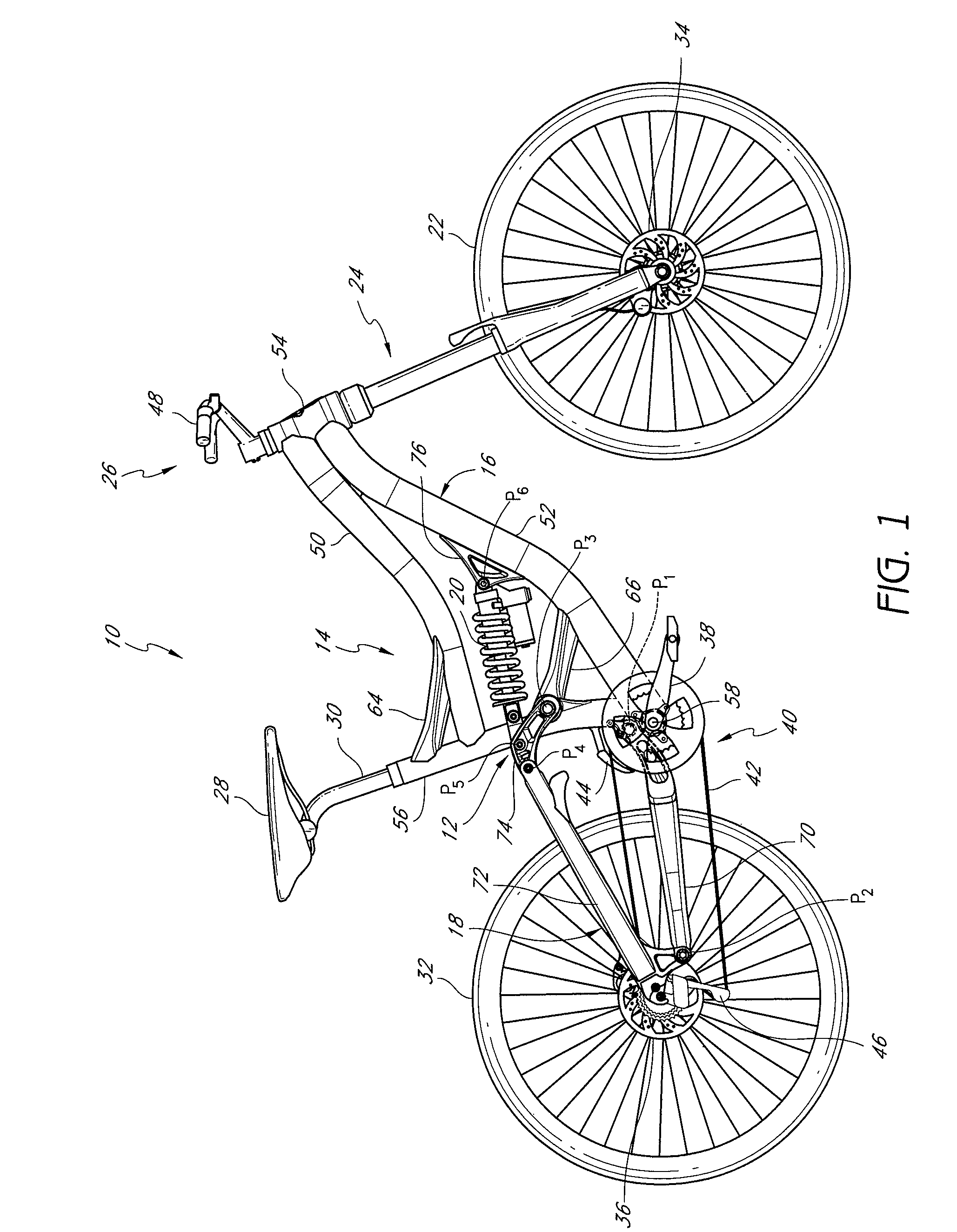
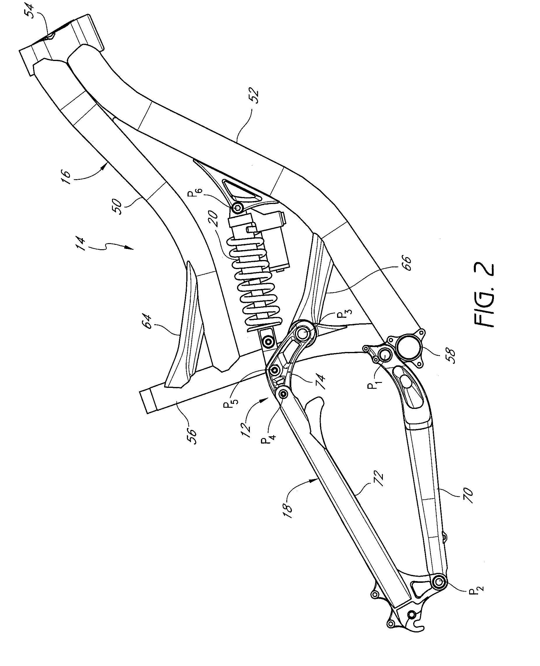
[0018]FIG. 1 illustrates a bicycle 10 including an articulating linkage mounting assembly having certain features, aspects and advantages of preferred embodiments of the present invention. The overall bicycle 10 is described in general detail to assist in the understanding of certain beneficial features and advantages of the illustrated embodiment of the articulating linkage mounting assembly 12. Details of the bicycle 10 that are not described herein may be assumed to be of a conventional construction or a suitable alternative construction, as will be appreciated by one of skill in the art. Although the present articulating linkage mounting assembly is described herein with respect to a bicycle application, it is contemplated that the mounting assembly may be adapted for use with other vehicles incorporating shock absorbers, such as motorcycles or automobiles, for example.

[0019]The bicycle 10 includes a frame assembly 14 which, preferably, includes a main frame portion 16 and an ar...


PUM


Abstract

A bicycle frame assembly includes an articulating linkage mounting arrangement that fixedly couples one or more lever arms to a rotatable axle. A preferred embodiment includes at least one lever arm, and preferably a pair of lever arms. The lever arm or arms are fixedly coupled to an axle by a fastener having a fastener axis that is eccentric to, or offset from, the axis of rotation of the axle. Accordingly, relative rotation of the lever arm and axle is prevented such that the axle and lever arm rotate together as a unit.

Description

BACKGROUND OF THE INVENTION[0001]1. Field of the Invention[0002]The present invention relates to bicycle frame assemblies. In particular, the present invention relates to a mounting arrangement for an articulating linkage, such as a link component of a rear suspension assembly.[0003]2. Description of the Related Art[0004]A common rear suspension arrangement for a bicycle frame assembly includes an articulating sub-frame having a lever assembly or link that couples a portion of the sub-frame to a main frame of the bicycle frame assembly. The link may also support one end of a shock absorber operably coupled between the main frame and the sub-frame. The link often includes a pair of lever arms, which are spaced from one another in a lateral direction and interconnected by a crossbar portion such that the lever arms move together as a unit. However, a disadvantage of such an arrangement is that a clearance space must be provided to accommodate the crossbar portion throughout the range ...

Claims


Application Information

Patent Timeline
Patent Type & Authority Patents(United States)
IPC IPC(8): B62K3/00
CPCB62K25/286B62K25/30
Inventor CHAMBERLAIN, JASON L.
Owner SPECIALIZED BICYCLE COMPONENTS INC
Learn More