
Adjustable tine clamp systems and methods

Active Publication Date: 2011-02-15
SAGE AUTOMATION
View PDF13 Cites 66 Cited by
  • Summary
  • Abstract
  • Description
  • Claims
  • Application Information

AI Technical Summary

Benefits of technology

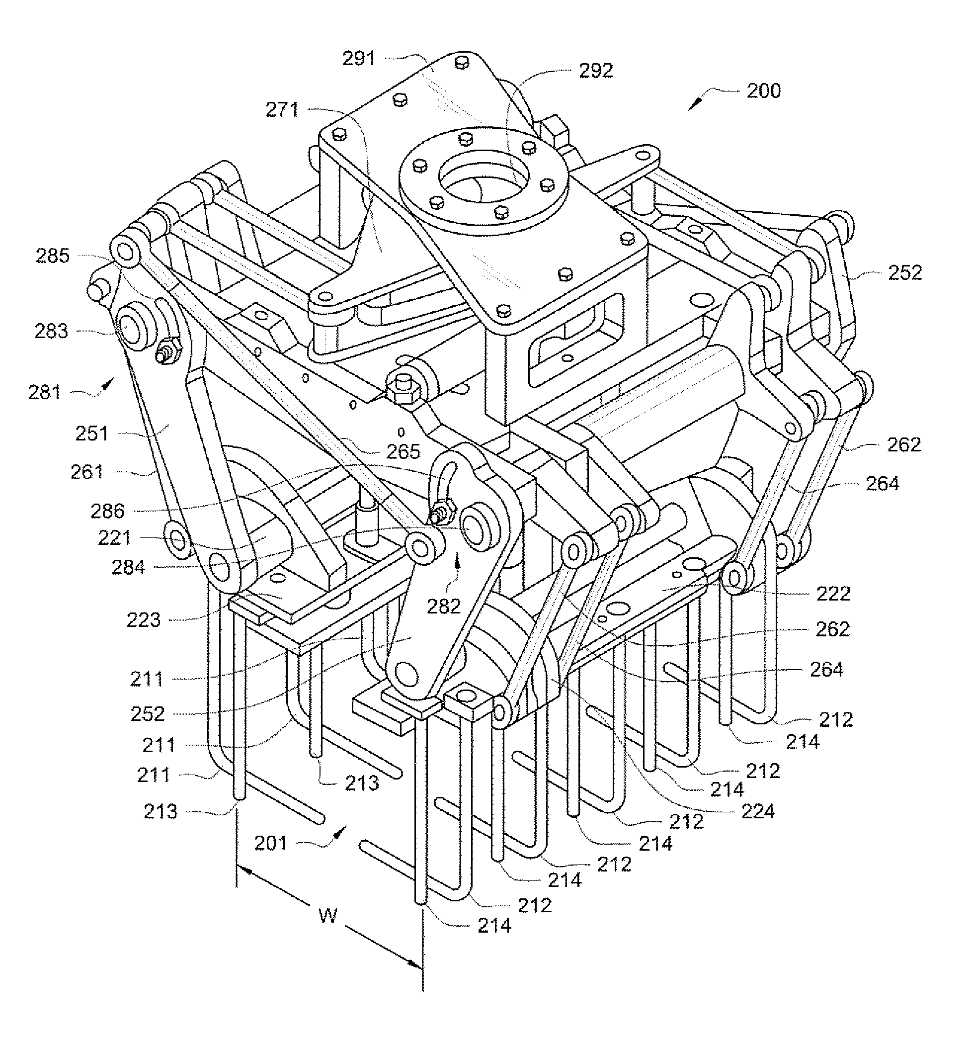
[0014]Preferred embodiments of the present invention utilize parallel links coupled to pivoting tine supports to maintain proper tine geometry throughout the full range of adjustment. Such parallel links are further utilized to actuate associated tines, through movement of the pivoting tine supports, in operation of the adjustable tine clamp according to embodiments of the invention. Parallel links implemented according to embodiments of the invention are adapted to maintain synchronous tine operation, regardless of adjustment of the adjustable support members. Accordingly, through adjustment of adjustable support members, without requiring any corresponding adjustment to the tines, their supports, or actuators, embodiments of the present invention may be easily and quickly adjusted to accommodate goods of different sizes and shapes.
[0015]Embodiments of the present invention further implement a short stroke actuator configura

Problems solved by technology

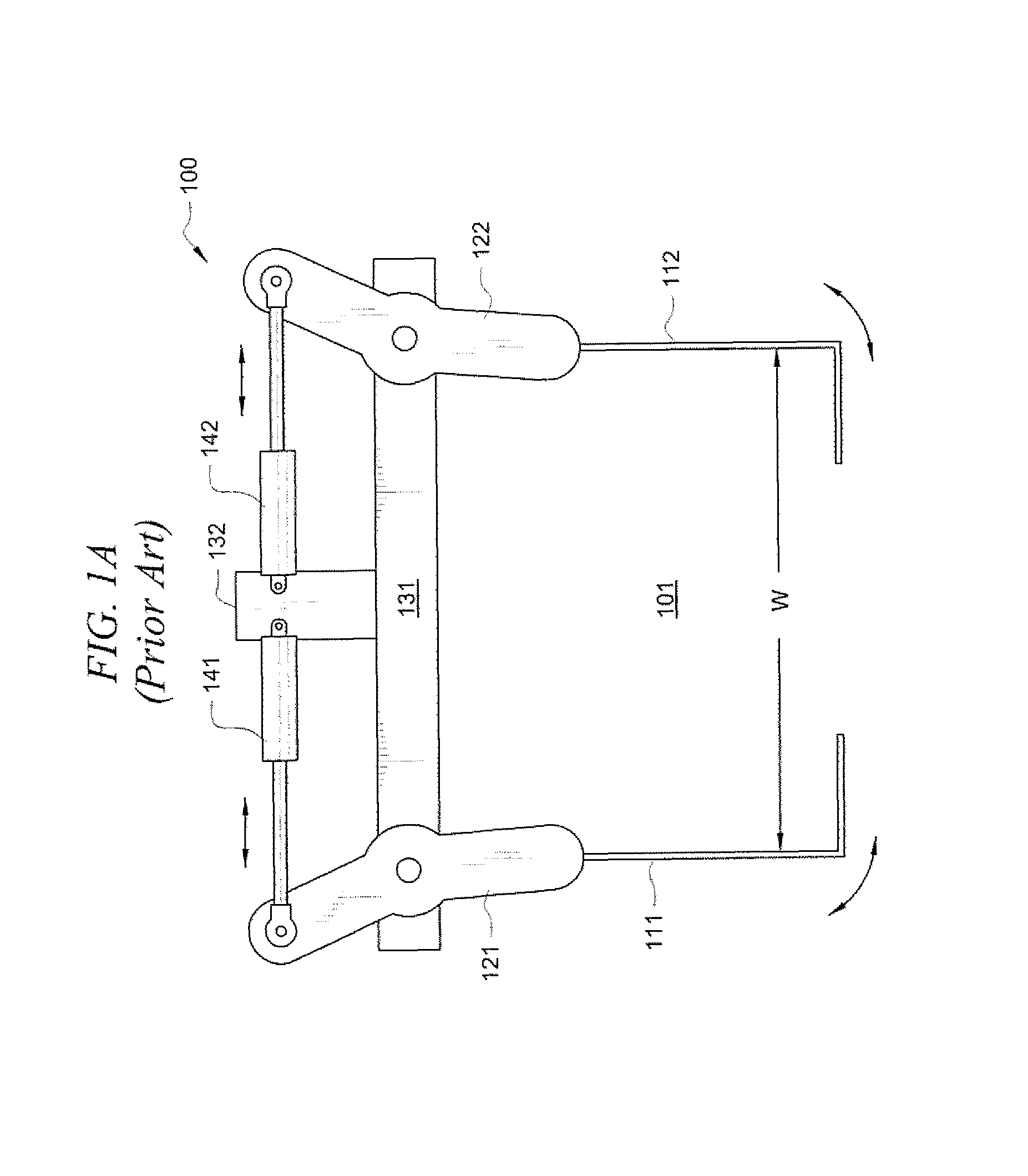
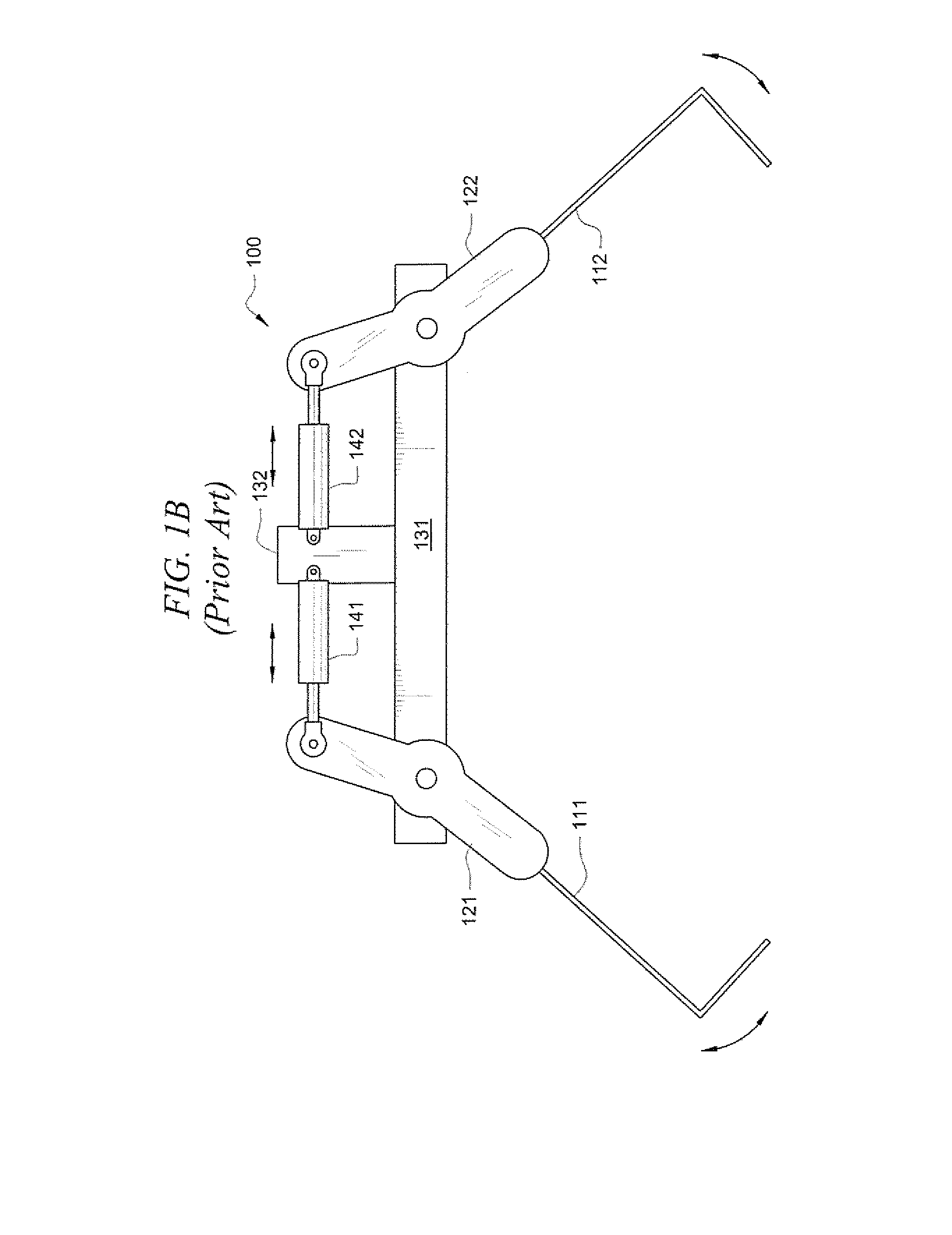
Such a configuration is problematic in that if the movement of the actuators, and thus the movement of the tines, is not synchronized the goods may be mishandled.
For example, angled tines 111 operating out of synchronization of angled tines 112 may cause goods disposed in basket area 101 to move left or right, thereby resulting in misplacement of the goods by the robotic actuator.
Such inaccurate placement of goods can result in damage to the goods, unorganized or unstable stacking of goods, etc.
If such goods were attempted to be manipulated by basket tine clamp 100, such handling would likely result in the failure to adequately incarcerate the goods during movement or processing, damage to the goods by basket tine clamp 100, etc.
Such a situation can lead to failure to adequately incarcerate the goods during movement or processing, damage to the goods by basket tine clamp 100, etc.
M

Method used


Image

  • Adjustable tine clamp systems and methods
  • Adjustable tine clamp systems and methods
  • Adjustable tine clamp systems and methods

Examples


Example

[0022]FIGS. 2A-2C show adjustable basket tine clamp 200 adapted to provide an adjustable tine clamp robotic manipulator according to an embodiment of the invention. Accordingly, adjustable basket tine clamp 200 as shown in FIG. 2A includes robotic arm attachment bracket 291 utilized for mounting adjustable basket tine clamp 200 on the end of a robotic arm member (not shown). Various control links (not shown), such as pneumatic lines, hydraulic lines, sensor and / or control electrical cables, etc., may be routed from a robotic control system via the robotic arm member, such as through bracket orifice 292, for coupling with components of adjustable basket tine clamp 200, such as actuators, sensors, etc.

[0023]Adjustable basket tine clamp 200 is preferably disposed on the end of a robotic arm member (not shown) to provide an interface with goods, while the robotic arm member is controlled to move adjustable basket tine clamp 200 and any goods disposed within basket area 201. Accordingly,...


PUM


Abstract

Systems and methods which provide an adjustable tine clamp configuration are shown. Embodiments provide an adjustable support member configuration which is adapted to maintain a desired geometry of tines throughout an adjustable range. The adjustable support members are preferably adjustable to provide selectable clamping widths, such as to accommodate manipulation of goods of different sizes and shapes. Embodiments utilize parallel links coupled to pivoting tine supports to maintain proper tine geometry throughout the full range of adjustment. Such parallel links are further preferably utilized to actuate associated tines in operation of the adjustable tine clamp. Embodiments further implement a short stroke actuator configuration to facilitate very rapid production cycles.

Description

TECHNICAL FIELD[0001]The present invention relates generally to automated handling of goods and, more particularly, to adjustable tine clamp systems and methods.BACKGROUND OF THE INVENTION[0002]A wide variety of goods are handled, such as during manufacturing or processing, by automated means. Such goods may include any number of different configurations having various sizes and shapes. For example, bags of different sizes, shapes, compositions, and external marking characteristics are used in various industries to encapsulate loose product so that the product can be efficiently consolidated, transported, distributed, and marketed. These bags are often manufactured and processed by automated means, such as to cut flattened tubes of appropriate lengths, seal an end or ends to form a bag or close a filled bag using stitching or adhesive, print information and other markings on a surface thereof, stack and pallet of the finished, unfilled bags, filling the bags with product, etc. Accor...

Claims


Application Information

Patent Timeline
IPC IPC(8): B25J15/00
CPCB25J15/022B25J15/026B25J15/0266
Inventor CAWLEY, CLIFTON M.STEPHENS, TIMOTHY W.
Owner SAGE AUTOMATION
Learn More