
Apparatus for chemiluminescent assay and detection

a technology of chemiluminescent assay and measuring apparatus, which is applied in the direction of material analysis through optical means, biomass after-treatment, instruments, etc., can solve the problems of increasing the distance between the sample container and the sensitive area, increasing the distance from the luminous point, and reducing sensitivity, so as to achieve high sensitivity and accuracy, and reduce the dependence on background signals. , the effect of high sensitivity

Active Publication Date: 2011-02-01
HITACHI LTD
View PDF11 Cites 12 Cited by
  • Summary
  • Abstract
  • Description
  • Claims
  • Application Information

AI Technical Summary

Benefits of technology

The present invention provides an apparatus for chemiluminescent assay and detection with high sensitivity and accuracy. The apparatus includes a container for storing a specimen, a holder for holding the container, a photodetector, a plate member driving section, and a photodetector position control section. The apparatus can measure the amount of microbes using a luminescence intensity of ATP in living microbes. The apparatus can also include a first light-shielding housing, a second light-shielding housing, a dispensing means, and a nozzle position control section. The double light shielding type box prevents light accumulation and reduces variations in background signals, while the proximity effect induced by a photodetector and the bottom of a sample container enables a quantitative measurement of ATP of a very low concentration. The apparatus is simple to operate and can be used for aseptic medical products and CPC.

Problems solved by technology

The shutter unit can be an obstacle which substantially increases the distance between a sample container and the sensitive area, and also increases the distance from a luminous point.
This may cause a problem of a decreased sensitivity.
In addition, the conventional methods described above could not provided a sufficiently high sensitivity or measurement accuracy for detecting ATP chemiluminescence on the order of one microbe level which is required in manufacturing facilities of aseptic medical products and CPC, and so generally involves a pre-treatment process for culturing to increase microbes.
This causes a problem that the processes become complicated and more than a half day is spent in the series of processes for obtaining the test result of cleanliness.

Method used


Image

  • Apparatus for chemiluminescent assay and detection
  • Apparatus for chemiluminescent assay and detection
  • Apparatus for chemiluminescent assay and detection

Examples


first embodiment

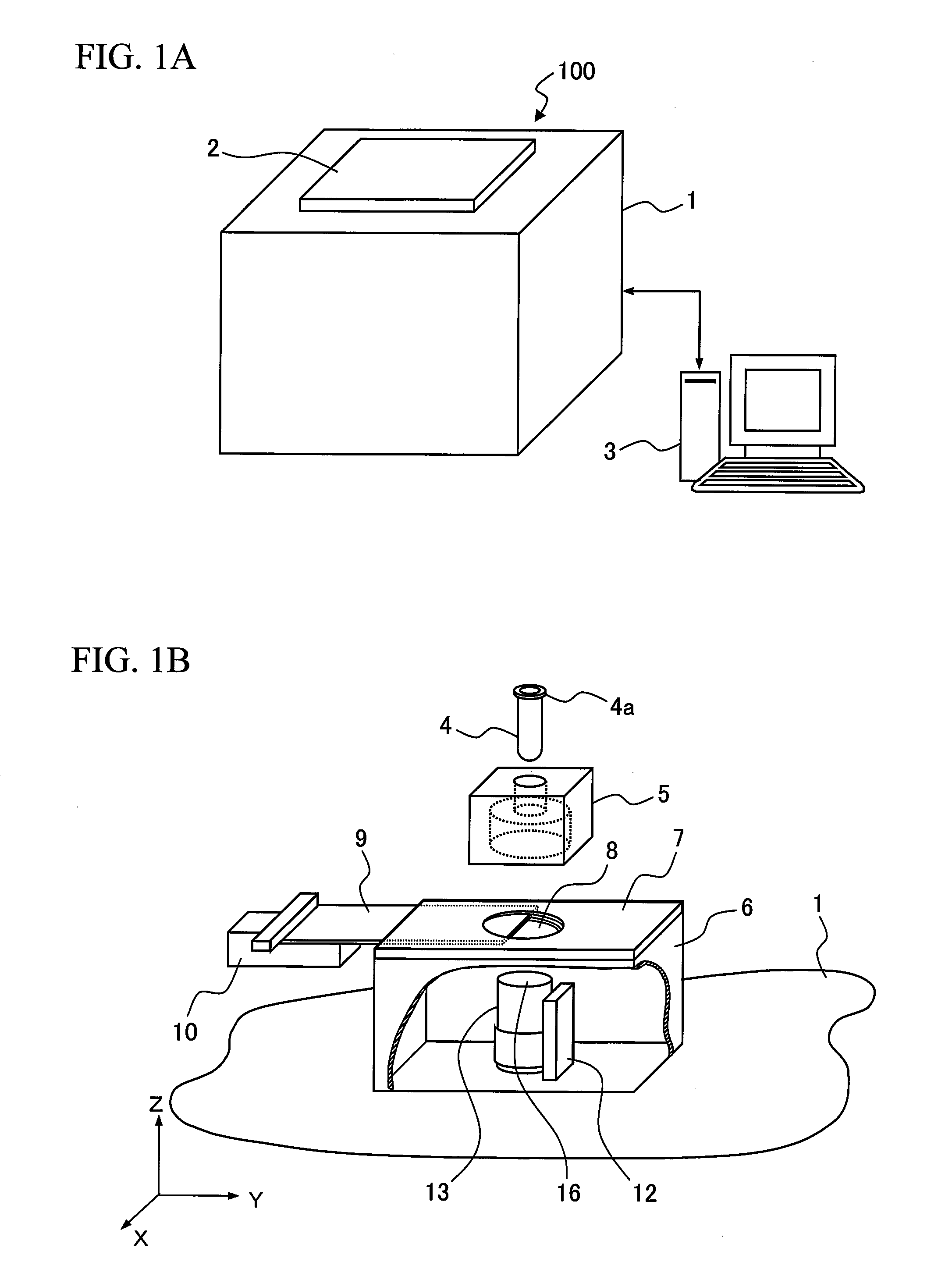
[0049]FIG. 1 is a schematic view showing a structure of an apparatus for chemiluminescent assay and detection according to a first embodiment. FIG. 1A is an outline view showing a system which includes a chemiluminescence measuring apparatus 100 and a control device 3 for controlling the chemiluminescence measuring apparatus 100. The chemiluminescence measuring apparatus 100 includes a first light shielding BOX 1 and an open / close door 2 which is opened / closed to install a sample container. The inner structure of the chemiluminescence measuring apparatus 100 is shown in FIG. 1B. FIG. 1B is shown as an exploded view for simplicity of illustration.

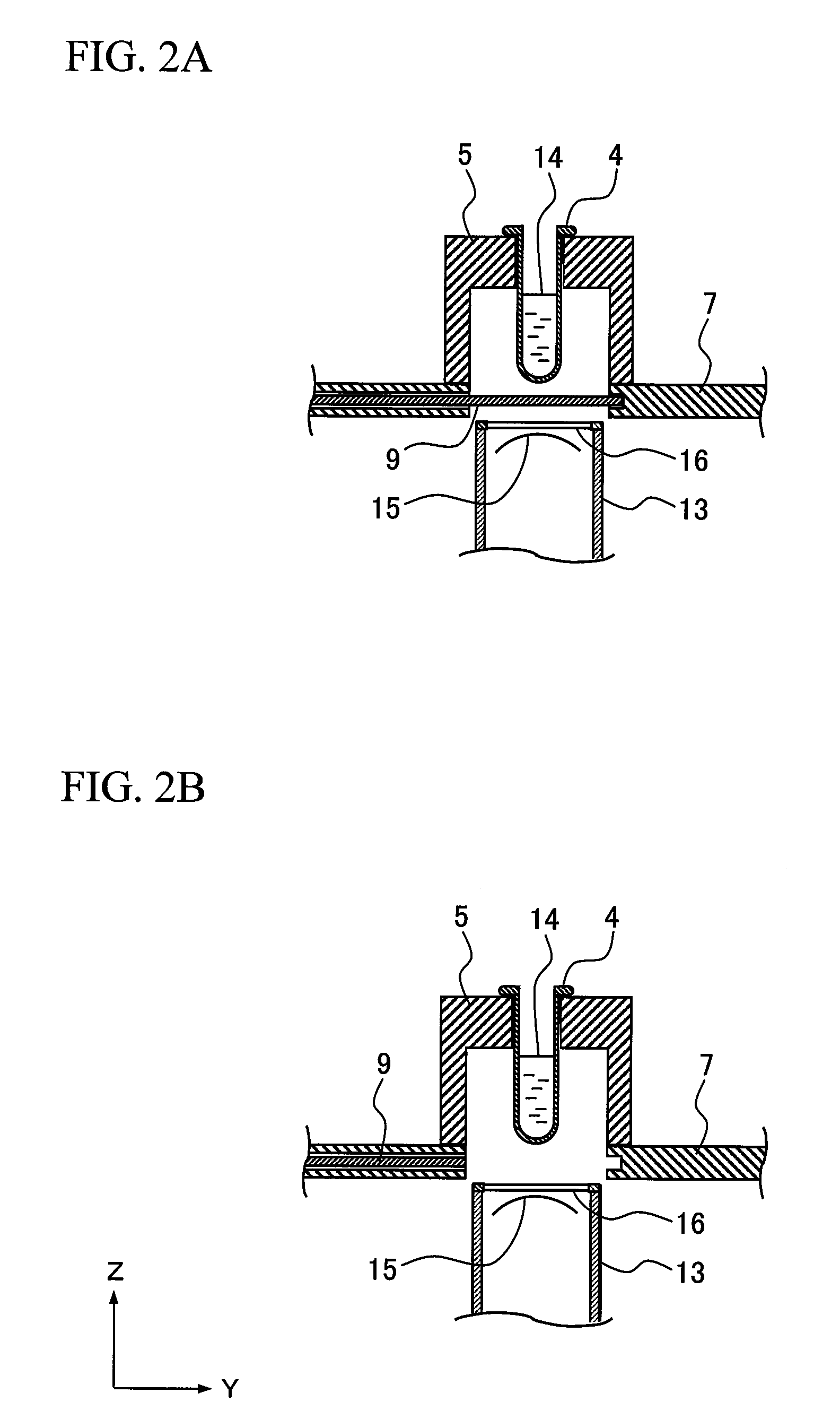
[0050]A sample container 4 is installed in a sample container holder 5. The sample container holder 5 is placed over a through hole 8 which is formed in a top plate 7 of a second light shielding BOX 6. The sample container holder 5 is configured to be positioned on the top plate 7 when placed thereon. For example, a frame may be provided to ...

second embodiment

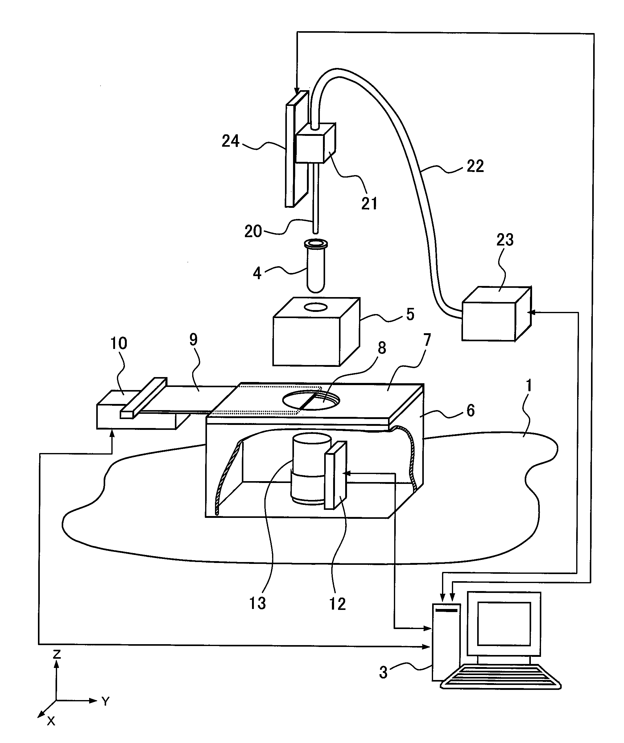
[0066]FIG. 4 is a view showing a schematic structure of an apparatus for chemiluminescent assay and detection according to a second embodiment. The apparatus for chemiluminescent assay and detection of the present embodiment includes a solution dispenser in addition to the structure of the first embodiment (a chemiluminescence measuring apparatus having a dispenser).

[0067]In FIG. 4, a sample container 4 is mounted to a sample container holder 5. The sample container holder 5 is placed over a through hole 8 which is formed in a top plate 7 of a second light shielding BOX 6. The sample container holder 5 is aligned in the same manner as that of the first embodiment.

[0068]The top plate 7 of the second light shielding BOX 6 is configured to have a plate member 9 inserted therethrough. The inserted plate member 9 is able to move in the direction of the y-axis through the top plate 7 by the first actuator 10. The through hole 8 functions as an openable / closable window for introducing chem...

third embodiment

[0084]A third embodiment relates to an apparatus for chemiluminescent assay and detection having a microbe count function for counting the number of living microbes. The apparatus selectively detects only ATP which is contained in the living microbes, and measures the amount of the ATP. The ATP content of each type of microbes is already known, thereby the number of microbes can be calculated based on the calibration curve of FIG. 7B according to the second embodiment. For example, the ATP content of one Escherichia coli is 2 amol to 3 amol.

[0085]FIGS. 8A and 8B and FIG. 9 are views showing the outline of a system including an apparatus for chemiluminescent assay and detection 50 having a microbe count function according to the third embodiment and the control device 3. The apparatus for chemiluminescent assay and detection 50 having a microbe count function is automatically controlled by the control device 3. The command from the control device 3 causes the openable / closable window...


PUM

PropertyMeasurementUnit
distanceaaaaaaaaaa
chemiluminescent assayaaaaaaaaaa
chemiluminescenceaaaaaaaaaa

Abstract

An apparatus includes a system for guiding chemiluminescence and a system for preventing a variation in dark currents. The apparatus includes a first light shielding BOX having a sample container holder and a shutter unit therein, the shutter unit including a top plate which is partly formed by a movement of a plate member and a second light shielding BOX having a photodetector therein. While a measurement is not implemented, the shutter unit is closed to block entrance of stray light to the photodetector, and while a measurement is implemented, the plate member is moved to open the shutter unit, and the tip of the photodetector is inserted into a through hole formed in the top plate, so that the distance between the bottom of the sample container and a sensitive area of the photodetector is reduced to several millimeters or less.

Description

CLAIM OF PRIORITY[0001]The present application claims priority from Japanese application JP 2007-112018 filed on Apr. 20, 2007, the content of which is hereby incorporated by reference into this application.BACKGROUND OF THE INVENTION[0002]1. Field of the Invention[0003]The present invention relates to a chemiluminescence measuring apparatus for detecting chemiluminescence and bioluminescence of a substance which is contained in a liquid specimen, with high sensitivity and accuracy. The present invention also relates to a microbe count function for detecting ATP chemiluminescence of microbes to control a contamination level.[0004]2. Background Art[0005]Microbe monitoring for environmental control of medicinal chemical manufacturing plants and the like involves counting of airborne microorganisms, falling microorganisms, and adherent microorganisms. The method for counting is defined by International Organization for Standardization ISO 14698-1, and the cleanliness measured by the me...

Claims


Application Information

Patent Timeline
Patent Type & Authority Patents(United States)
IPC IPC(8): G01N21/76G01N21/75G01N21/00G01N33/48G01N33/00G01N15/06
CPCC12Q1/04G01N21/76G01N21/763
Inventor NODA, HIDEYUKIOZAWA, SATOSHIOKANOJO, MASAHIROUCHIDA, KENKO
Owner HITACHI LTD
Learn More