Indoor unit of air conditioner

a technology for indoor units and air conditioners, which is applied in the field of indoor units of air conditioners, can solve the problems of limiting the layout space, and restricting the arrangement of indicating devices, so as to reduce the layout space of operating devices and indicating devices

Inactive Publication Date: 2011-02-01
DAIKIN IND LTD
View PDF14 Cites 10 Cited by
  • Summary
  • Abstract
  • Description
  • Claims
  • Application Information

AI Technical Summary

Benefits of technology

[0008]It is an object of the present invention to provide a wall-hung type indoor unit of an air conditioner in which a signal transmitted from a remote controller can be reliably received by a receiving device even when the receiving device has to be disposed at a bottom side of the indoor unit or in the vicinity thereof because of the configuration of the indoor unit.
[0010]With this indoor unit of the air conditioner, the receiving device is provided facing the first surface inclined upward so as to form an angle of 30 degrees or less with respect to the horizontal plane, and the receiving device is disposed such that the centerline of the receiving device is inclined to the plane perpendicular to the first surface and is also directed diagonally downward. Thus the centerline of the receiving device is directed in the forward direction of the casing. Accordingly, even when the receiving device has to be disposed at the bottom portion of the indoor unit or in the vicinity thereof because of the configuration of the indoor unit, a signal transmitted from the remote controller can be reliably received by the receiving device.
[0014]With this indoor unit of the air conditioner, the receiving device is disposed behind the indicating device, in other words, the indicating device is disposed in front of the receiving device, and thereby the centerline of the receiving device can be directed in the forward direction of the casing while securing the visibility of the indicating device.
[0016]With this indoor unit of the air conditioner, the receiving device is disposed behind the indicating device, in other words, the indicating device is disposed in front of the receiving device, and thereby the centerline of the receiving device can be directed in the forward direction of the casing while securing the visibility of the indicating device. In addition, with this indoor unit of the air conditioner, since the distance in a front-back direction between the lower end of the front panel and the lower end of the receiving device can be increased, a signal transmitted from a remote controller can be reliably received.
[0018]With this indoor unit of the air conditioner, the receiving device and the indicating device are mounted on the different substrates, and thus flexibility in installation of each substrate increases. Therefore, it is easy to dispose the receiving device such that the centerline of the receiving device is inclined to the plane perpendicular to the first surface and is also directed diagonally downward.
[0024]With this indoor unit of the air conditioner, since the operating device is mounted on the substrate on which the indicating device is mounted, the layout space of the operating device and the indicating device can be reduced.

Problems solved by technology

When such a structure provided with the front panel that can be opened and closed is employed, or when the receiving device has to be disposed at the bottom portion of the casing or in the vicinity thereof depending on the configuration of the indoor unit, such as the shape of the indoor unit or the restriction in equipment arrangement, a problem is caused that a signal transmitted from the remote controller cannot be reliably received by the receiving device.
These equipments also need be disposed at the bottom portion of the casing or in the vicinity thereof, which consequently limits the layout space.
In particular, since visibility needs to be secured for the indicating device, there are many restrictions in arrangement of the indicating device at the bottom portion of the casing or in the vicinity thereof.

Method used


Image

  • Indoor unit of air conditioner
  • Indoor unit of air conditioner
  • Indoor unit of air conditioner

Examples


Embodiment Construction

[0037]An embodiment of an indoor unit of an air conditioner according to the present invention is described below with reference to the drawings.

(1) STRUCTURE OF THE INDOOR UNIT OF AIR CONDITIONER

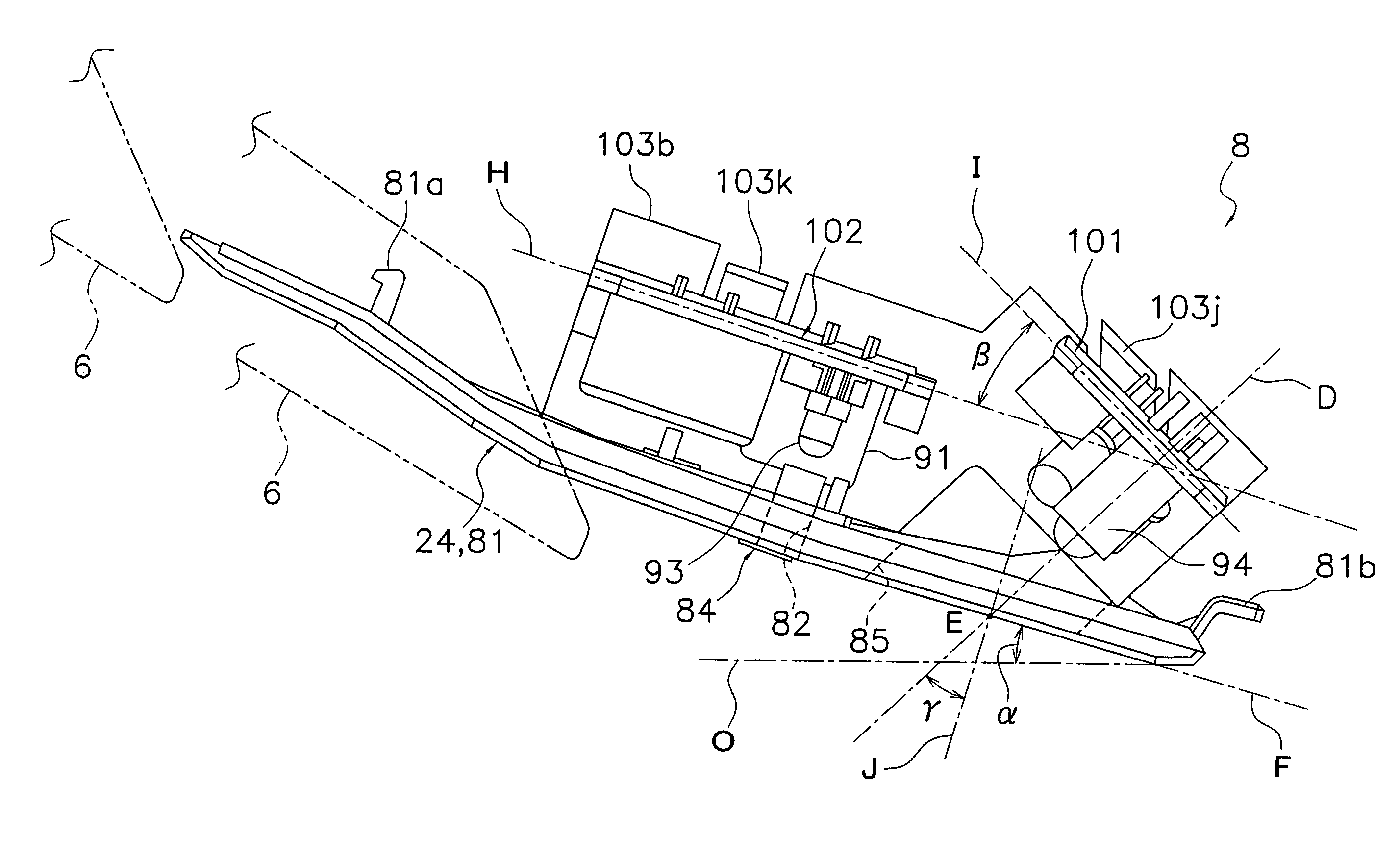
[0038]FIG. 1, FIG. 2, and FIG. 3 show an external view of an indoor unit 1 of an air conditioner according to an embodiment of the present invention. Note that in the description below, when direction and position for the indoor unit 1 are indicated, related terms are used with a state in which the indoor unit 1 is attached to a wall of a room as a reference. In addition, a side of the indoor unit 1 attached to the wall is regarded as a rear side of the indoor unit 1 (i.e., a casing 2), a side opposing the rear side and projecting into the room is regarded as a front side (or the front), lateral sides of the front side and the rear side are regarded as lateral sides (more specifically, a right side viewed from the front is regarded as a right lateral side, and a left side viewed from the fr...


PUM


Abstract

A wall-hung type indoor unit includes a casing having an air inlet for indoor air at a front side thereof, and a receiving element provided at a lower portion of the casing and configured to receive a signal transmitted from a remote controller. The casing having a first surface facing the receiving element. The first surface is inclined upward so as to form an angle α of 30 degrees or less with respect to a horizontal plane in a state in which the casing is attached to the wall. The receiving element is disposed such that a centerline of the receiving element is inclined with respect to an orthogonal plane perpendicular to the first casing surface. The centerline is directed diagonally downward.

Description

CROSS-REFERENCE TO RELATED APPLICATIONS[0001]This U.S. National stage application claims priority under 35 U.S.C. §119(a) to Japanese Patent Application No. 2004-323861, filed in Japan on Nov. 8, 2004, the entire contents of which are hereby incorporated herein by reference.TECHNICAL FIELD[0002]The present invention relates to an indoor unit of an air conditioner. More specifically, the present invention relates to a wall-hung type indoor unit of an air conditioner.BACKGROUND ART[0003]As one type of indoor unit that constitutes a separate type air conditioner, there is known a wall-hung type indoor unit attached to an upper portion of a wall of a room. This wall-hung type indoor unit is provided with a receiving device comprising infrared receiving elements and the like for receiving a signal transmitted from a remote controller such that the indoor unit can be operated by the remote controller. The receiving device is usually provided to be directed in the forward direction of the ...

Claims


Application Information

Patent Timeline
Patent Type & Authority Patents(United States)
IPC IPC(8): F25D23/12F24F1/008F24F13/20
CPCF24F1/0007F24F13/20F24F2011/0068F24F2013/207F24F11/56F24F1/008F24F11/89F24F11/52
Inventor YASUTOMI, MASANAO
Owner DAIKIN IND LTD
Why Eureka
Try Eureka