
Machine for forming, filling and closing bags with a bag lifting device

a lifting device and bag technology, applied in the direction of liquid materials, transportation and packaging, packaging goods, etc., can solve the problems of considerable lifting of the sack in the filling station, and achieve the effect of reducing dust or dust formation

Inactive Publication Date: 2011-02-01
WINDMOELLER & HOELSCHER GMBH
View PDF15 Cites 23 Cited by
  • Summary
  • Abstract
  • Description
  • Claims
  • Application Information

AI Technical Summary

Benefits of technology

The purpose of this invention is to create a tool that reduces dust and dirt caused by filling materials.

Problems solved by technology

The technical problem addressed in this patent is how to effectively package and remove dust-like products without compromising the quality and stability of the finished product, while also reducing waste and environmental impacts caused by excessive air usage and difficulty in storing the final product.

Method used


Image

  • Machine for forming, filling and closing bags with a bag lifting device
  • Machine for forming, filling and closing bags with a bag lifting device
  • Machine for forming, filling and closing bags with a bag lifting device

Examples


Embodiment Construction

[0019]Further scope of applicability of the present invention will become apparent from the detailed description given hereinafter. However, it should be understood that the detailed description and specific examples, while indicating preferred embodiments of the invention, are given by way of illustration only, since various changes and modifications within the spirit and scope of the invention will become apparent to those skilled in the art from this detailed description.

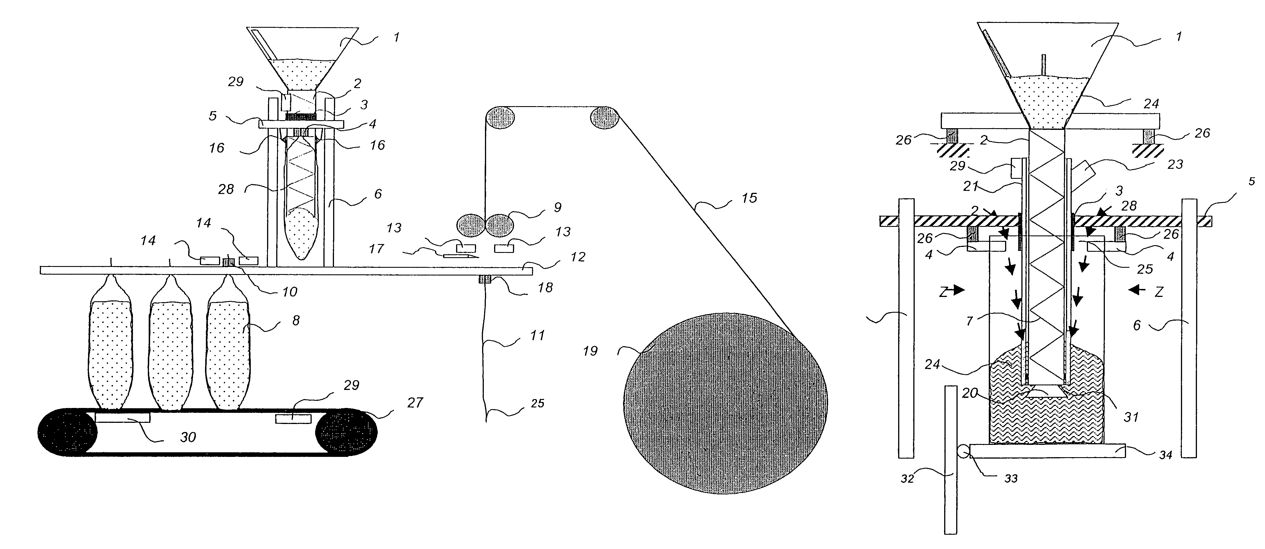
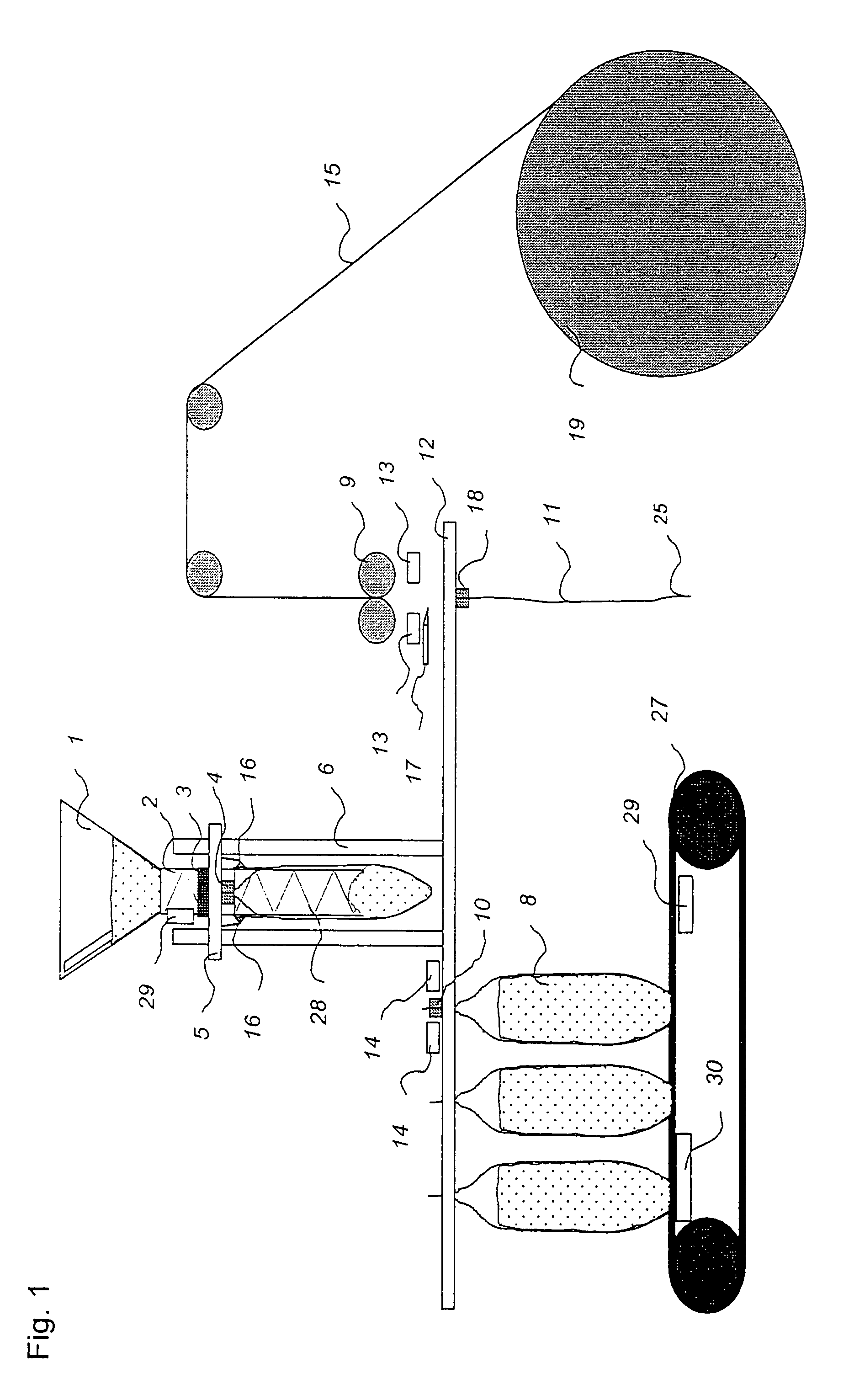
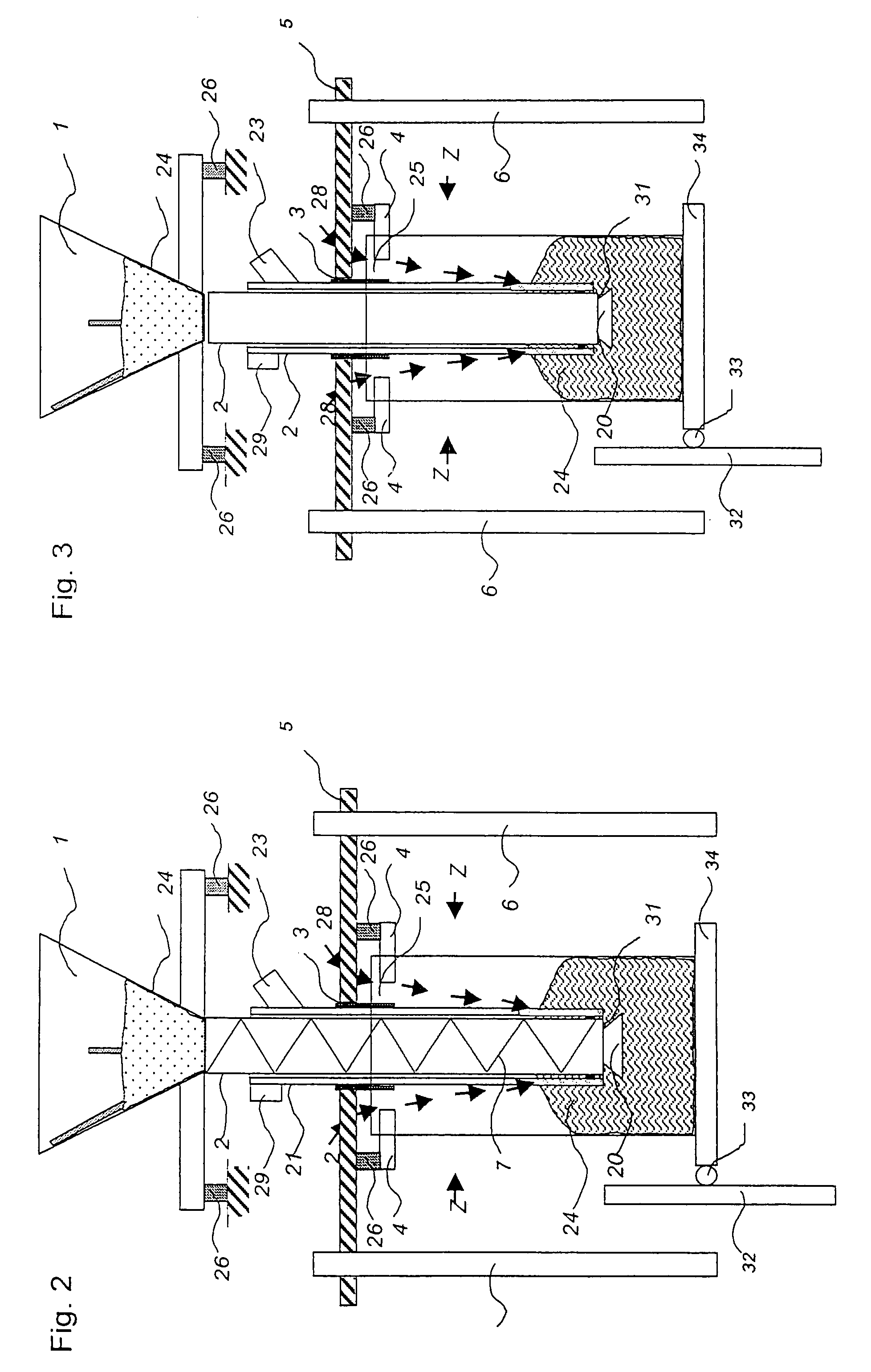
[0020]A tube foil web 15, preferably with inserted side fold, is first conveyed into a horizontally moving transport means 9, e.g. a gripper pair 18, by virtue of a roller system.

[0021]The foil web 15 is cut by a knife 17 after the section corresponding to the desired sack length is drawn. The bottom welding 13 takes place simultaneously. The empty sack 11 sealed at the lower end is transferred to a horizontally moving transport means, e.g., a gripper 18 and transported to the filling station.

[0022]Here, another ...


PUM

PropertyMeasurementUnit
Weightaaaaaaaaaa
Timeaaaaaaaaaa
Flow rateaaaaaaaaaa

Abstract

A machine for forming, filling, and sealing sacks has an unwinding device for a plastic tube, a cross-cutting device that cuts the tube perpendicularly to its principal axis of symmetry and creates tubular pieces in the process, a bottom forming means for forming a sack bottom at one end of the tubular piece, transport equipment to transport the resulting sacks through the machine, a filling station with a feeding element for filling the product in the sack, means of reducing the distance between the product discharge opening of the feed element and the bottom of the sack to be filled, and sealing means to seal the filled sack. The means of reducing the distance is a sack lifting device with which the sack can be lifted in the filling station such that an upper edge of the sack is located above the product discharge opening of the feed element.

Description


Claims


Application Information

Patent Timeline
Owner WINDMOELLER & HOELSCHER GMBH
Learn More