
Substrate processing apparatus

a processing apparatus and substrate technology, applied in the direction of lighting and heating apparatus, charge manipulation, furnaces, etc., can solve the problems of substrate pollution, limit the number of process chambers that can be provided to the conventional substrate processing apparatus, and the inability to connect the processing chamber

Inactive Publication Date: 2011-01-25
TOKYO ELECTRON LTD
View PDF14 Cites 17 Cited by
  • Summary
  • Abstract
  • Description
  • Claims
  • Application Information

AI Technical Summary

Benefits of technology

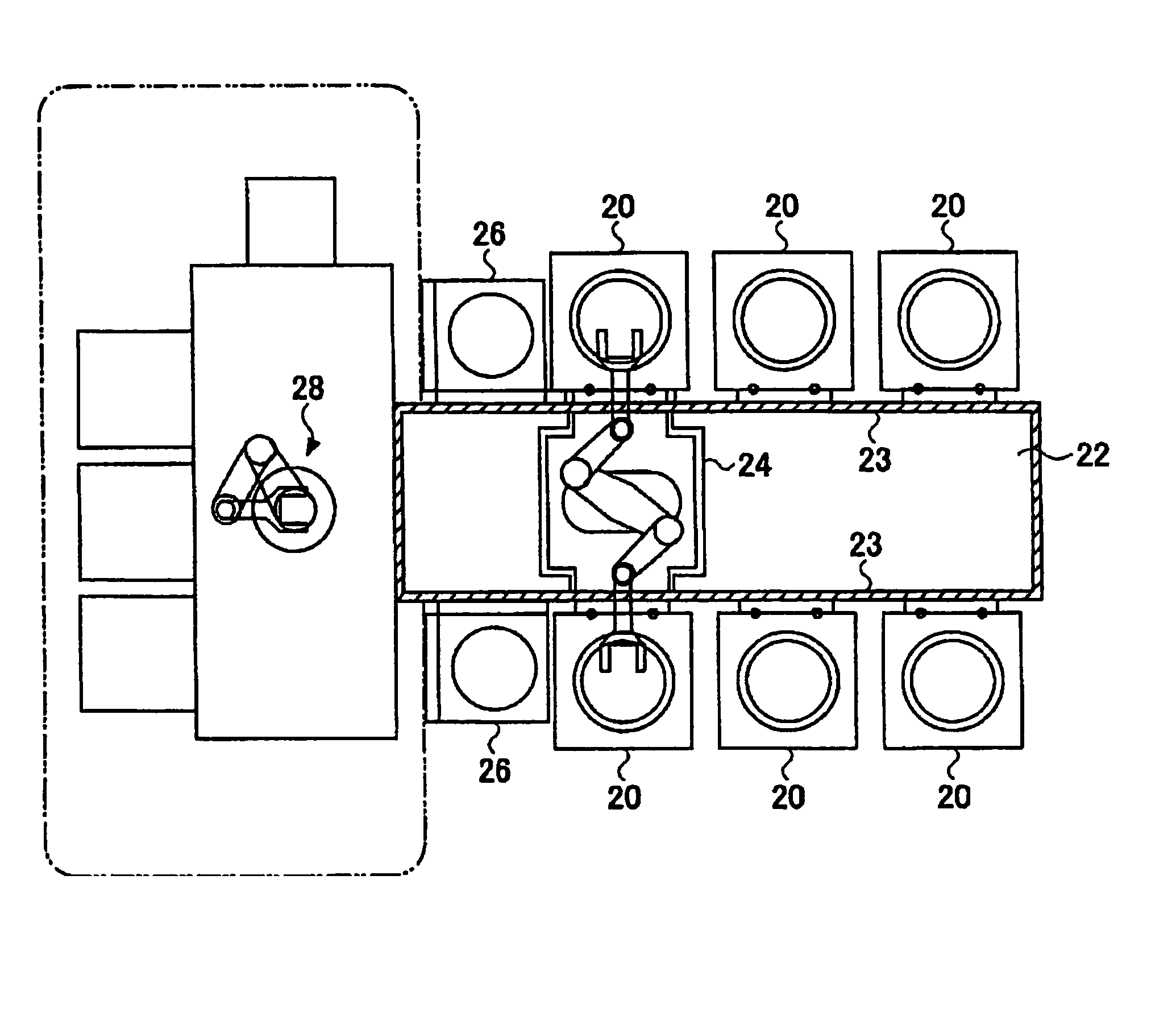
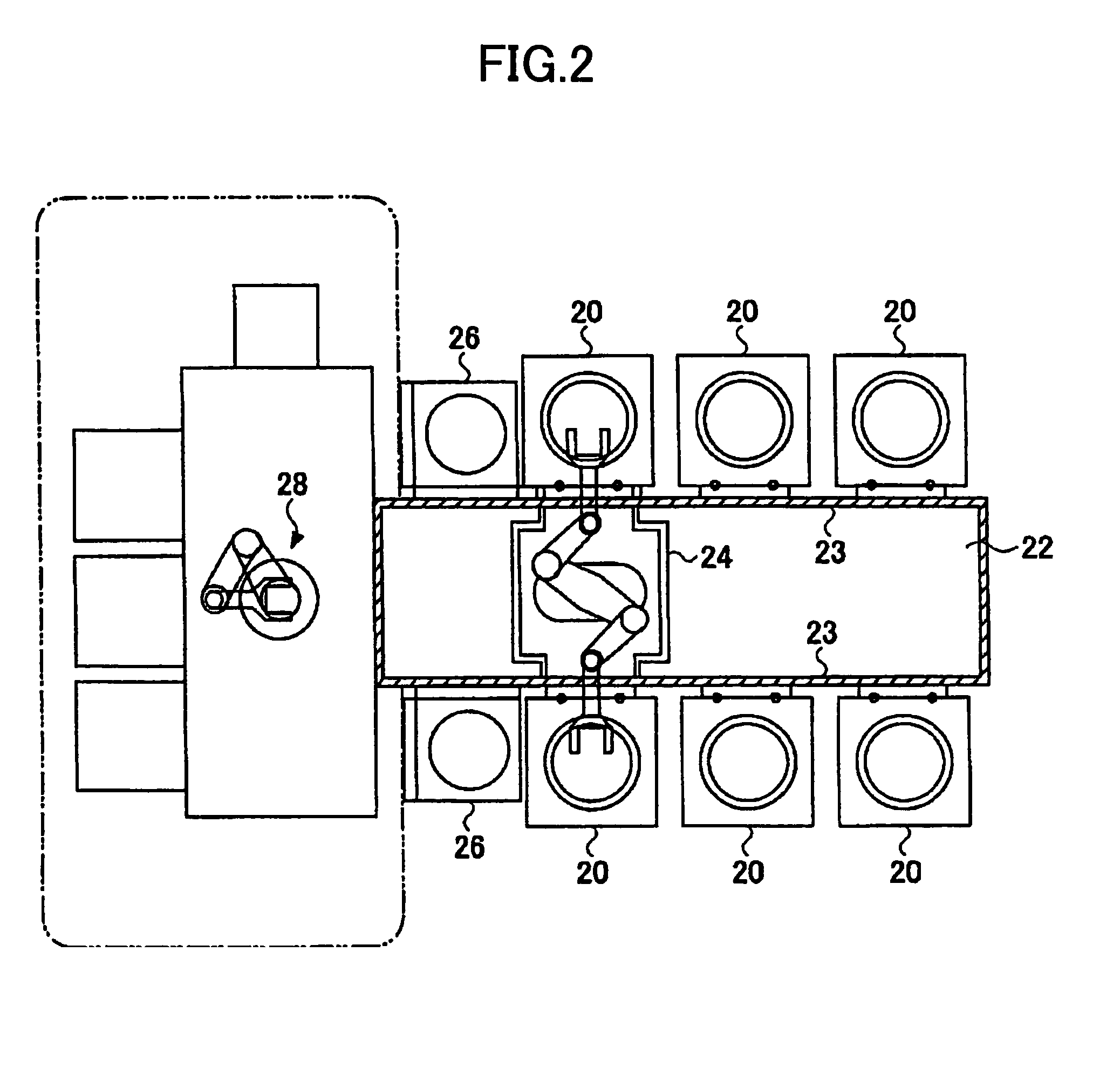
[0028]As mentioned above, according to the present invention, the substrates can be carried to the plurality of process chambers while maintaining an atmosphere of the substrates to be processed at a predetermined environment, and an installation area of the entire apparatus can be reduced. Additionally, there is no restriction in the number of process chambers to connect due to a configuration of the conveyance chamber, and an arbitrary number of process chambers and different processing apparatuses may be arranged along a conveyance path.

Problems solved by technology

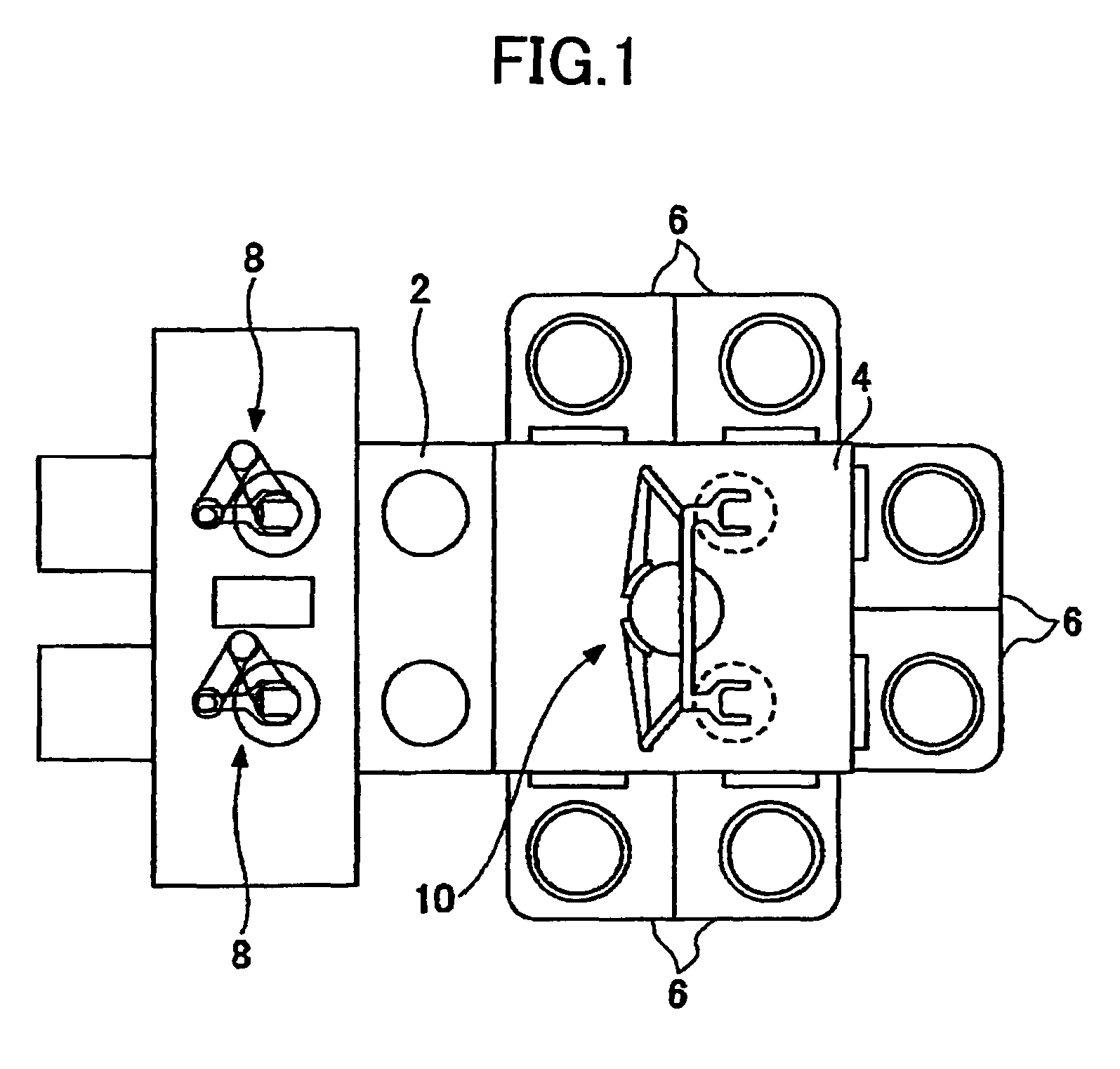
Although the number of sides to which the process chambers are connectable is increased by making the configuration of the conveyance chamber to be a polygonal shape of more than hexagon, one side may be smaller than a size of the process chamber, and, as a result, the process chamber cannot be connected.
Thus, there is a limit in the number of process chambers that can be provided to the conventional substrate processing apparatus, and there is a problem in that it cannot deal with a process to continuously performing many steps or a process to concurrently perform a large amount of processes each having one or plurality of steps.
However, since the transfer mechanism moves in the conveyance chamber which is to be maintained at a vacuum and clean atmosphere, the transfer mechanism may be a generation source of particles.
Especially, there is a problem in that particles may be generated by a cable for supplying electric power to the transfer mechanism being drawn, which is a cause of pollution of substrates.
Moreover, if the number of process chambers is increased, a space of the conveyance chamber is also increased, and there is a problem in that a pump having a large exhaust capacity is needed to maintain such as large space under a reduced pressure environment, which increases a cost.
Further, there also is a problem in the entire apparatus is enlarged by enlargement of the conveyance chamber, which results in an increase in an area occupied by the apparatus.

Method used


Image

  • Substrate processing apparatus
  • Substrate processing apparatus
  • Substrate processing apparatus

Examples


first embodiment

[0103]Next, a description will be given of a variation of the substrate processing apparatus according to the present invention.

[0104]FIG. 8 is an outline plan view of a first variation of the substrate processing apparatus shown in FIG. 2. In this variation, process chambers 80 which perform a different process from that of the process chambers 20 are connected to the conveyance chamber 22. Substrates processed in the process chambers 20 are further conveyed to the process chambers 80 by the conveyance case 24, and are conveyed to outside from the substrate processing apparatus after performing a subsequent process. Accordingly, a plurality of processes can be applied to substrates in a single substrate processing apparatus.

[0105]FIG. 9 is an outline plan view showing a second variation of the substrate processing apparatus shown in FIG. 2. In this variation, the load-lock chamber 26 is divided into two with respect to one row of the process chambers 20. Additionally, two conveyanc...

second embodiment

[0113]As mentioned above, in the substrate processing apparatus according to the present embodiment, since the load-lock chamber can be omitted, the entire substrate processing apparatus becomes small and an installation area can be reduced.


PUM

PropertyMeasurementUnit
timeaaaaaaaaaa
poweraaaaaaaaaa
pressureaaaaaaaaaa

Abstract

A substrate processing apparatus includes a plurality of process chambers (20) for applying a process to substrate accommodated therein and a conveyance case (24) that conveys the accommodated substrates to the process chambers (20) and a transfer mechanism that moves the conveyance case (24) along a moving path. The conveyance case accommodates the substrates in an isolated state from an external atmosphere. The plurality of process chambers (20) are arranged in an aligned state on both sides of a moving path of the conveyance case (24). The conveyance case (24) has two conveyance ports (24a) in response to conveyance ports (20a) of the process chambers (20) arranged in alignment in two rows.

Description

TECHNICAL FIELD[0001]The present invention relates to substrate processing apparatuses and, more particularly, to a substrate processing apparatus having a moving mechanism that conveys a substrate such as a semiconductor wafer or the like to a process chamber that processes the wafer under a predetermined environment.BACKGROUND ART[0002]In processing a substrate such as a semiconductor wafer or the like, many processes to supply a process gas under a predetermined reduced pressure atmosphere are used. In many cases, such a process is performed while placing a substrate in a process chamber which can maintain a reduced pressure atmosphere. Processing a substrate generally includes a plurality of processes, and a plurality of process chambers for performing those processes are connected to a substrate conveyance chamber and the substrate is carried into a process chamber and carried out of the process chamber by a conveyance mechanism such as a robot so as to be conveyed to another p...

Claims


Application Information

Patent Timeline
Patent Type & Authority Patents(United States)
IPC IPC(8): H01L21/677H01L21/00B65G49/00H01L21/68
CPCH01L21/67167H01L21/67173H01L21/67742Y10S414/139H01L21/68B65G49/00
Inventor NOZAWA, TOSHIHISAMATSUOKA, TAKAAKI
Owner TOKYO ELECTRON LTD
Learn More