
Adjustable cycle pipeline system and method

Active Publication Date: 2010-12-28
NVIDIA CORP
View PDF5 Cites 7 Cited by
  • Summary
  • Abstract
  • Description
  • Claims
  • Application Information

AI Technical Summary

Problems solved by technology

However, infrequent operations requiring relatively long periods of time to execute typically have a disproportionate adverse impact on the overall performance of traditional pipeline approaches.
A purely sequential system typically requires a lot more time to complete a series of operations since one operation is not performed until the preceding operation is completed.
These manipulations often involve numerous computational processes some of which are completed relatively quickly and others take a relatively long time to complete.
Slow rendering rates often cause undesirable choppy or “jerky” presentations which usually results in a user experience that is non-immersive and unpleasant.
Conventional attempts at addressing pipeline timing are usually inefficient and / or resource intensive.
This approach tends to be relatively simplistic but tends to slow down the throughput of whole device.
Some traditional pipeline systems attempt to address pipeline cycle time by adding hardware resources to speed up the pipeline which increases cost.
However, these approaches also add two cycles to every operation or require sophisticated tracking to know that results of some execution operations can not be used until two cycles later.
However, these attempts typically end up consuming more power and typically take longer to complete operations.
In addition, trying to analyze and test self-timed logic is very complicated and resource intensive.
However, in self-timed circuits there is usually a domino effect in that something that happens in one part of the chip feeds back and forth with other parts of the chip.

Method used


Image

  • Adjustable cycle pipeline system and method
  • Adjustable cycle pipeline system and method
  • Adjustable cycle pipeline system and method

Examples


Embodiment Construction

[0013]Reference will now be made in detail to the preferred embodiments of the invention, examples of which are illustrated in the accompanying drawings. While the invention will be described in conjunction with the preferred embodiments, it will be understood that they are not intended to limit the invention to these embodiments. On the contrary, the invention is intended to cover alternatives, modifications and equivalents, which may be included within the spirit and scope of the invention as defined by the appended claims. Furthermore, in the following detailed description of the present invention, numerous specific details are set forth in order to provide a thorough understanding of the present invention. However, it will be obvious to one of ordinary skill in the art that the present invention may be practiced without these specific details. In other instances, well known methods, procedures, components, and circuits have not been described in detail as not to unnecessarily ob...


PUM


Abstract

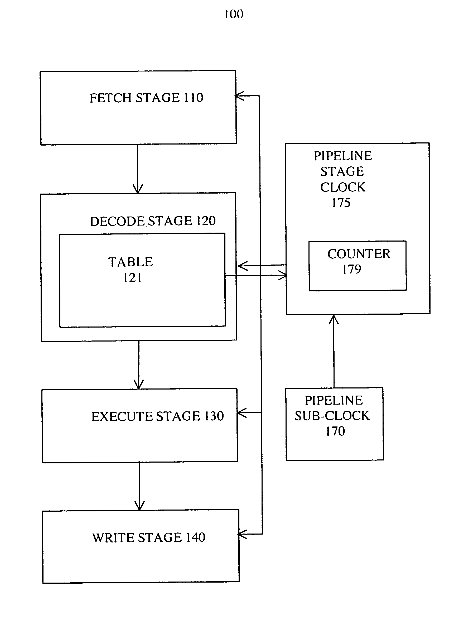
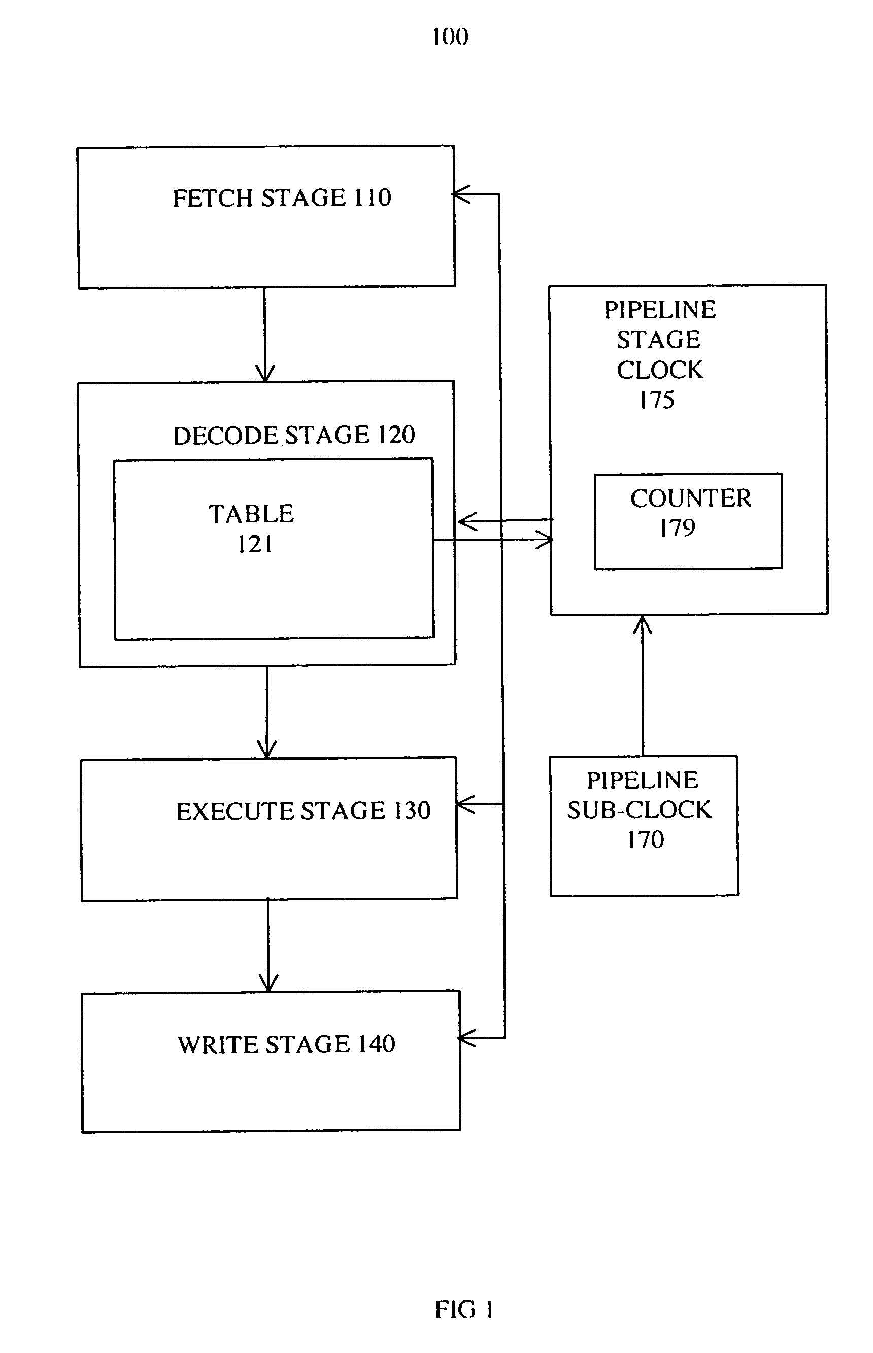
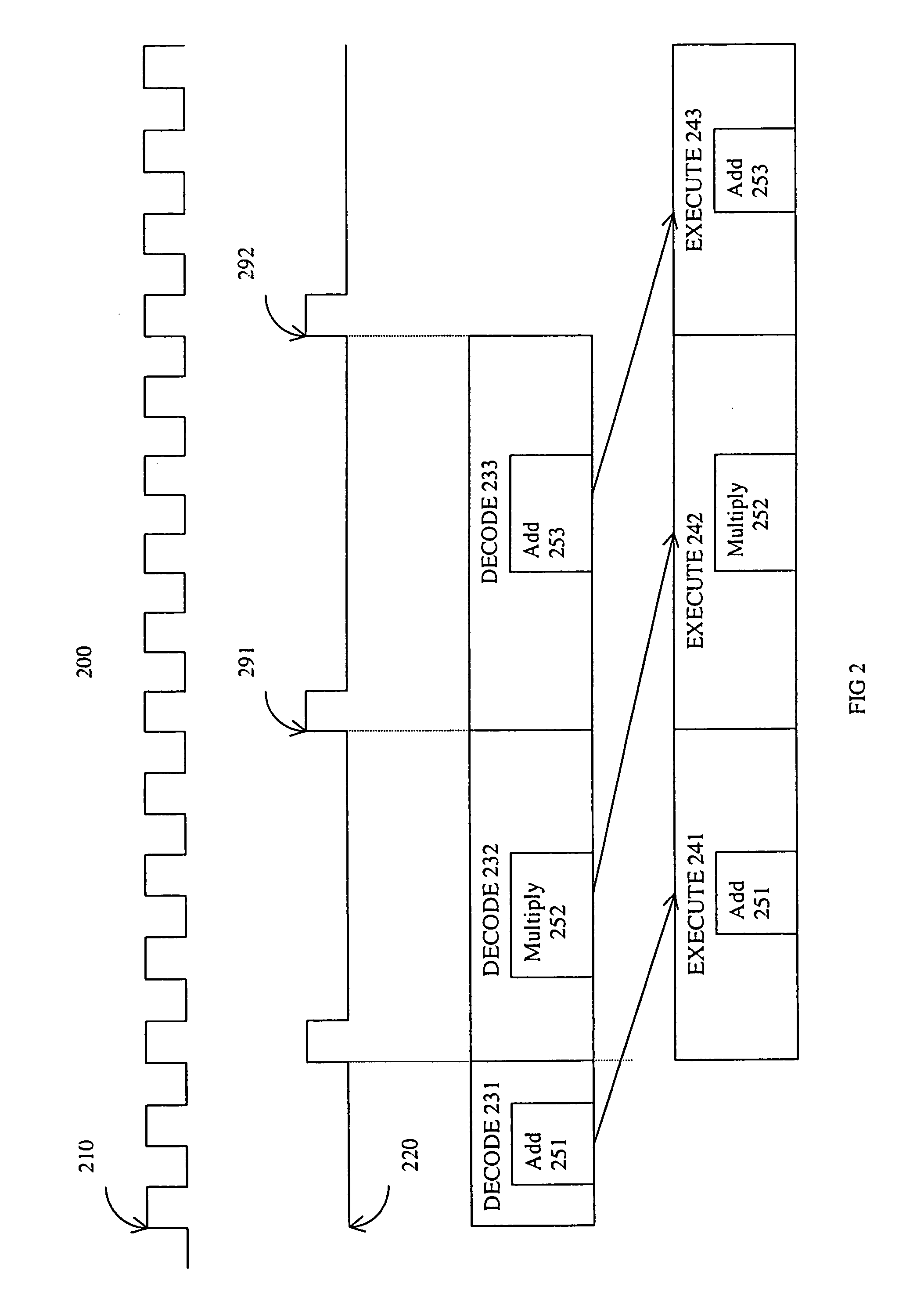
The present invention utilizes an asynchronous pipeline cycle to facilitate increased average pipeline processing speed. Present invention adjustable cycle pipeline systems and methods minimize “stalls” in execution stages that would otherwise be required to compensate for differences in execution periods. In one embodiment, an adjustable cycle pipeline system includes a fetch stage, a decode stage, an execution stage, and a write stage. The fetch stage fetches information associated with an operation. The decode stage decodes the instructions including determining an instruction execution period. The execution stage executes instructions in accordance with the execution period and the write stage writes the results. In one exemplary implementation the instruction execution period corresponds to a particular number execution sub-clock cycles and the decode stage includes a decode operation timetable for indicating a period of time to complete execution of an operation. The sub-clock controls operations of the execution stage.

Description

FIELD OF THE INVENTION[0001]The present invention relates to the field of information processing. More particularly the present invention relates to a sub-clock pipeline system and method.BACKGROUND OF THE INVENTION[0002]Electronic systems and circuits have made a significant contribution towards the advancement of modern society and are utilized in a number of applications to achieve advantageous results. Numerous electronic technologies such as digital computers, calculators, audio devices, video equipment, and telephone systems have facilitated increased productivity and reduced costs in analyzing and communicating data, ideas and trends in most areas of business, science, education and entertainment. Frequently, these activities involve information processing with demands for greater performance and functionality increases. Pipelining the operations is one approach often utilized to increase performance. However, infrequent operations requiring relatively long periods of time to...

Claims


Application Information

Patent Timeline
IPC IPC(8): G06F9/00
CPCG06F9/30145G06F9/3869G06F9/3871
Inventor CHAYUT, IRA
Owner NVIDIA CORP
Learn More