
System for selective display of airport traffic information

a technology for airport traffic and information, applied in the field of system for selective display of airport traffic information, can solve the problems of difficult reading, more and more problems of orientation and security, and difficulty in reading

Inactive Publication Date: 2010-12-28
THALES SA
View PDF7 Cites 11 Cited by
  • Summary
  • Abstract
  • Description
  • Claims
  • Application Information

AI Technical Summary

Benefits of technology

[0005]An object of the present invention is to remedy this disadvantage by limiting the transfer of traffic to an airport traffic map displayed on a flight deck to the elements most pertinent to a taxiing aid and a protection of the ground movements of the aircraft that is in possession of the same.

Problems solved by technology

The complexity of the pattern of runways and thoroughfares of certain airports and their increasingly heavy traffic are posing more and more problems of orientation and of security for an aircraft moving on their thoroughfares in poor visibility conditions at night or in bad weather.
These airport traffic map displays with transfers of the current positions of the aircraft and of the surrounding traffic poses the problem of legibility.
However, it remains that, in an airport zone with heavy traffic, a large number of mobiles and in particular all the aircraft having their on-board instruments in operation, whether they are parked or moving, communicate their positions and registration numbers that are transferred to the traffic map displayed on the flight deck, making it hard to read.

Method used


Image

  • System for selective display of airport traffic information
  • System for selective display of airport traffic information
  • System for selective display of airport traffic information

Examples


Embodiment Construction

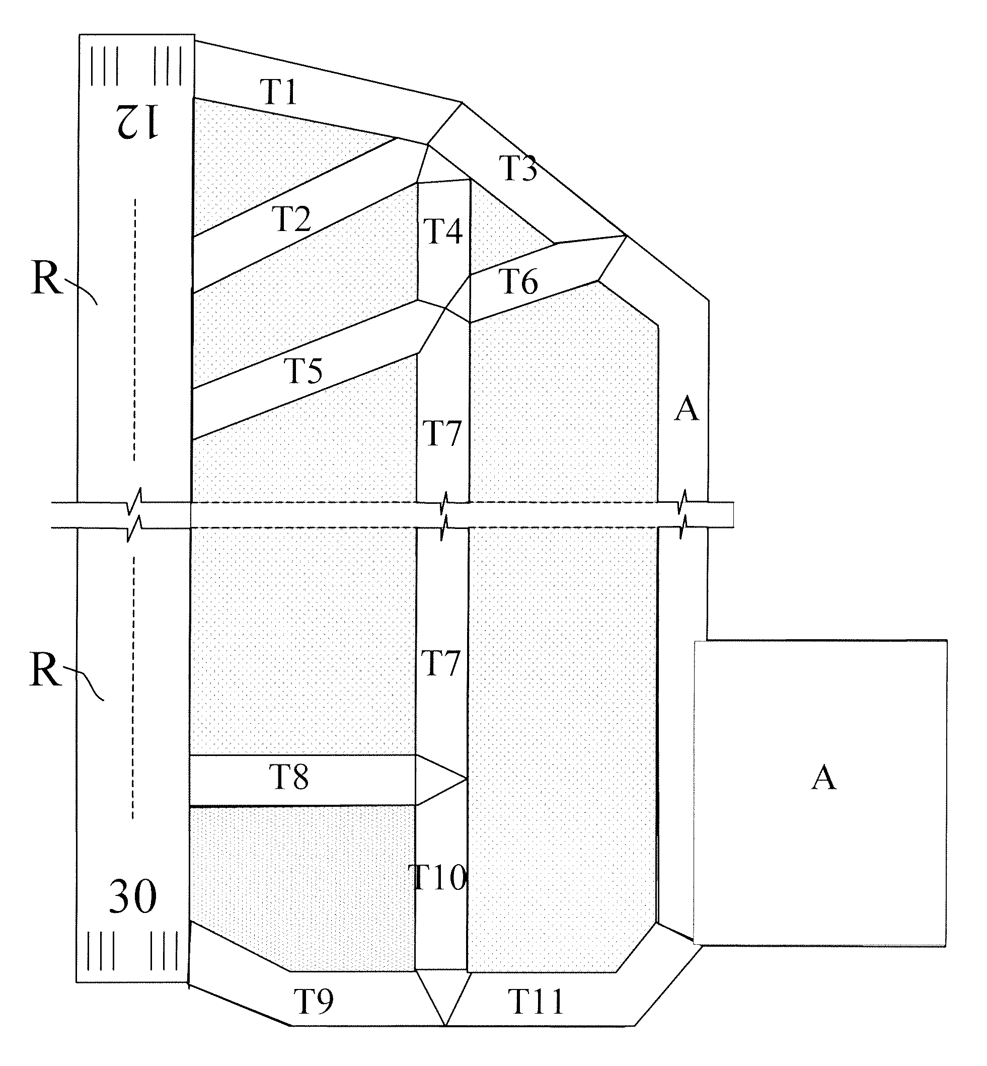
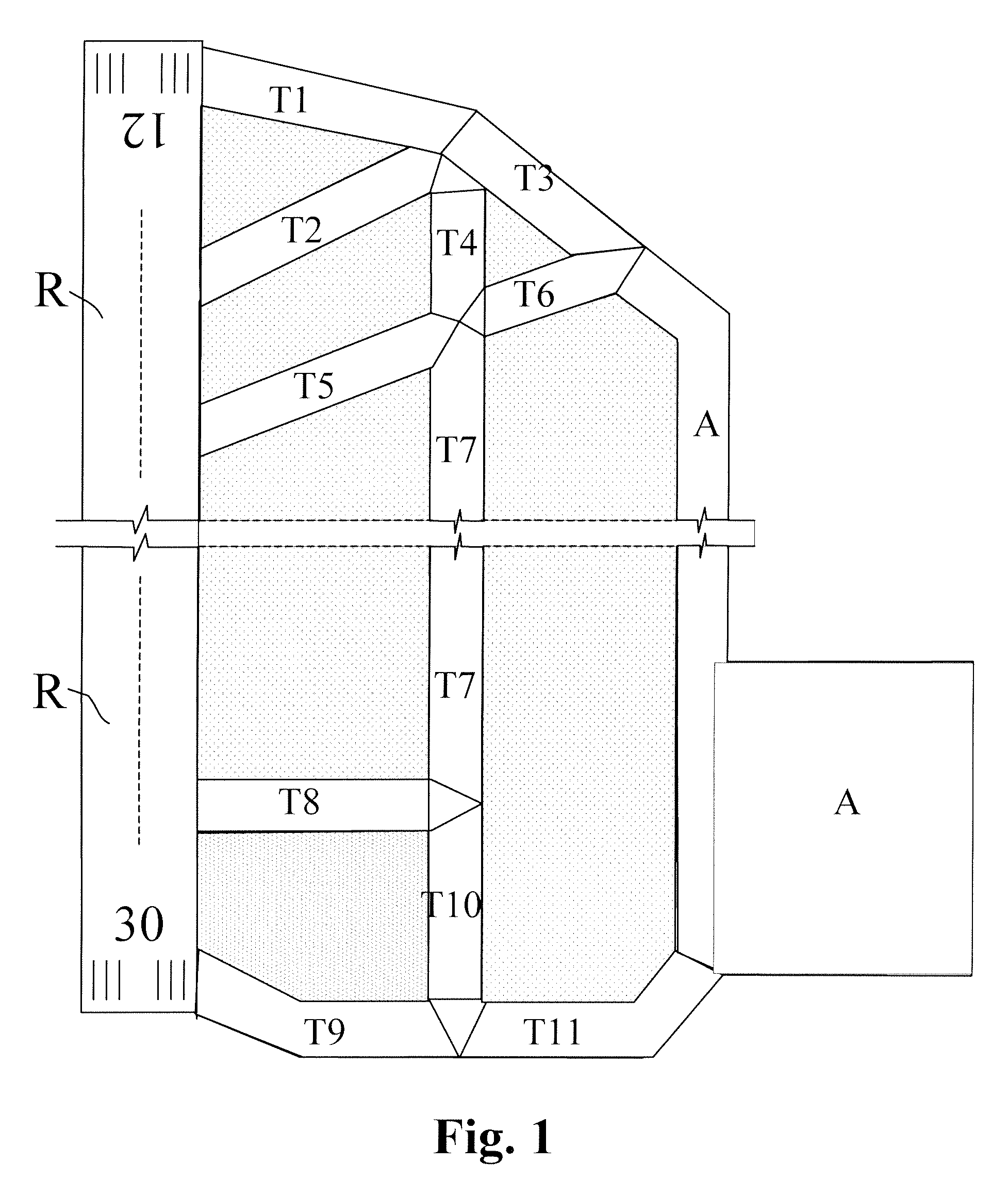
[0032]FIG. 1 shows an airport configuration with a landing and take-off runway R and a parking area A for the aircraft. The runway R is duplicated, on the parking area A side, by a parallel taxiway divided, for its identification, into three successive sections T4, T7 and T10. It is connected by end taxiways, divided, for their identification, into two successive sections T1, T3 and T9, T11 to the ends of the parallel taxiway T4, T7, T10 then, beyond that, to the parking area A. It is also connected to the parallel taxiway T4, T7, T10 by intermediate clearing taxiways T2, T5, T8, two of which culminate in an end taxiway T1, T3, one of them T2 directly, the other T5 by means of another taxiway T6 placed in its extension.

[0033]The division of the taxiways into sections corresponds to the intersections or, as for the taxiway section T11, to mandatory stopping points, “stop bars”, that may be passed only with the authorization of an authority controlling the airport traffic.

[0034]This t...


PUM


Abstract

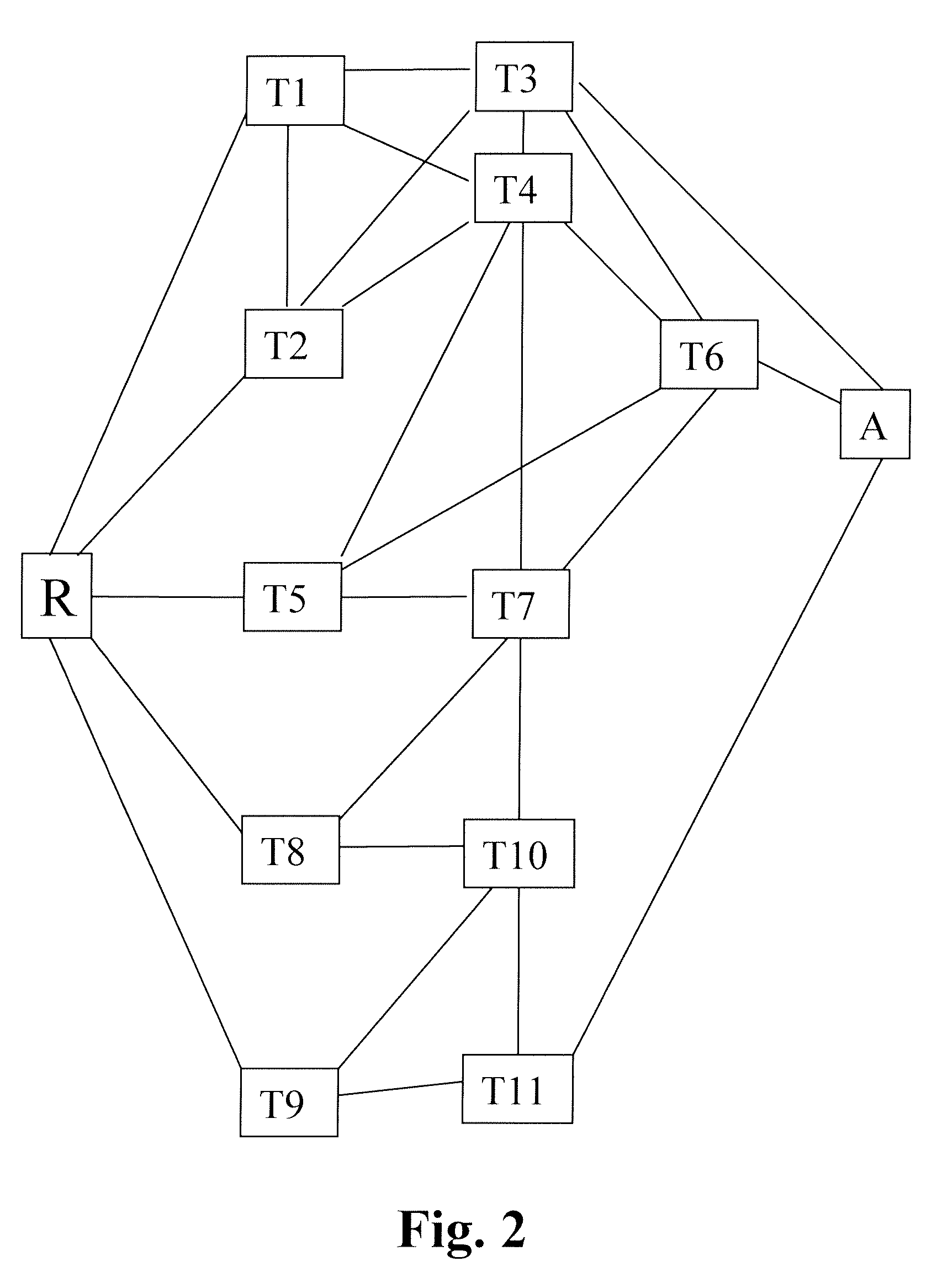
This system for displaying, on the flight deck of an aircraft travelling on the surface of an airport, an airport map mentioning the surface traffic, for the purpose of a taxiing aid and protection of the ground movements of the aircraft, shows on the airport map only the traffic occupying the airport thoroughfares close to the aircraft, this closeness being defined by the existence of a joining path comprising a number of thoroughfare sections that is less than an arbitrary limit of the order of 1 or 2.

Description

RELATED APPLICATIONS[0001]The present application is based on, and claims priority from, French Application Number 06 11088, filed Dec. 20, 2006, the disclosure of which is hereby incorporated by reference herein in its entirety.FIELD OF THE INVENTION[0002]The present invention relates to the display, on the flight deck of an aircraft travelling on the surface of an airport, of an airport map mentioning the surface traffic, for the purpose of a taxiing aid and a protection of the ground movements of the aircraft.BACKGROUND OF THE INVENTION[0003]The complexity of the pattern of runways and thoroughfares of certain airports and their increasingly heavy traffic are posing more and more problems of orientation and of security for an aircraft moving on their thoroughfares in poor visibility conditions at night or in bad weather. To remedy this, it has been proposed to display on a screen of an aircraft flight deck a map of the thoroughfares of the airport in which it is moving, drawn fro...

Claims


Application Information

Patent Timeline
Patent Type & Authority Patents(United States)
IPC IPC(8): G06F19/00
CPCG01C23/00G08G5/065
Inventor MEUNIER, HUGUES
Owner THALES SA
Learn More