
Ion energy spread reduction for mass spectrometer

a mass spectrometer and ion energy technology, applied in mass spectrometers, isotope separation, particle separator tubes, etc., can solve the problems of limited success of the fragmentation device that carries out the fragmentation of parent ions, and many ion optical devices can only function well, so as to reduce the energy spread of ions and reduce the energy spread of said ions

Active Publication Date: 2010-12-28
THERMO FISHER SCI BREMEN
View PDF47 Cites 32 Cited by
  • Summary
  • Abstract
  • Description
  • Claims
  • Application Information

AI Technical Summary

Benefits of technology

The present invention provides a method and apparatus for reducing the energy spread of ions over a specific mass to charge ratio range. This is achieved by using an ion deceleration electrode arrangement to generate an electric field and directing ions of a specific mass to charge ratio range into this electric field. The electric field strength is matched to the energy spread of the ions upon entry into the electric field, resulting in a reduction in energy spread. The invention can be used in combination with an ion selection device and a fragmentation device, and can also be used in a cyclical arrangement where ions are trapped, cooled, and ejected back into the ion storage device for further use. The invention provides a cost and control saving over existing methods and reduces the number of MS stages required, improving ion transport efficiency.

Problems solved by technology

Many ion optical devices can only function well with ions having energies within a limited energy range.
Successful operation of the fragmentation device that carries out fragmentation of parent ions is likewise limited by the degree of energy spread of ions that enter it.

Method used


Image

  • Ion energy spread reduction for mass spectrometer
  • Ion energy spread reduction for mass spectrometer
  • Ion energy spread reduction for mass spectrometer

Examples


Embodiment Construction

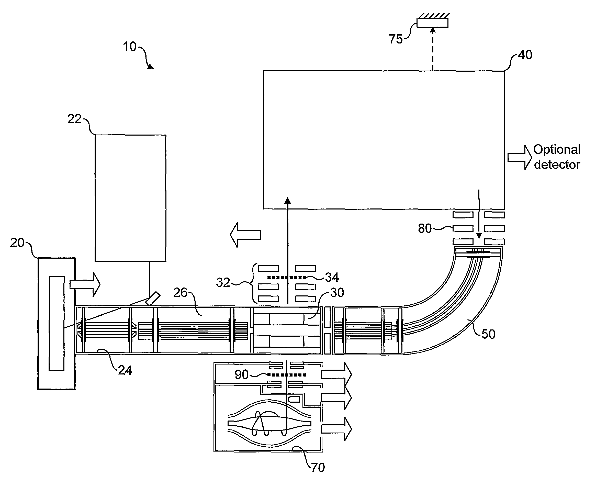
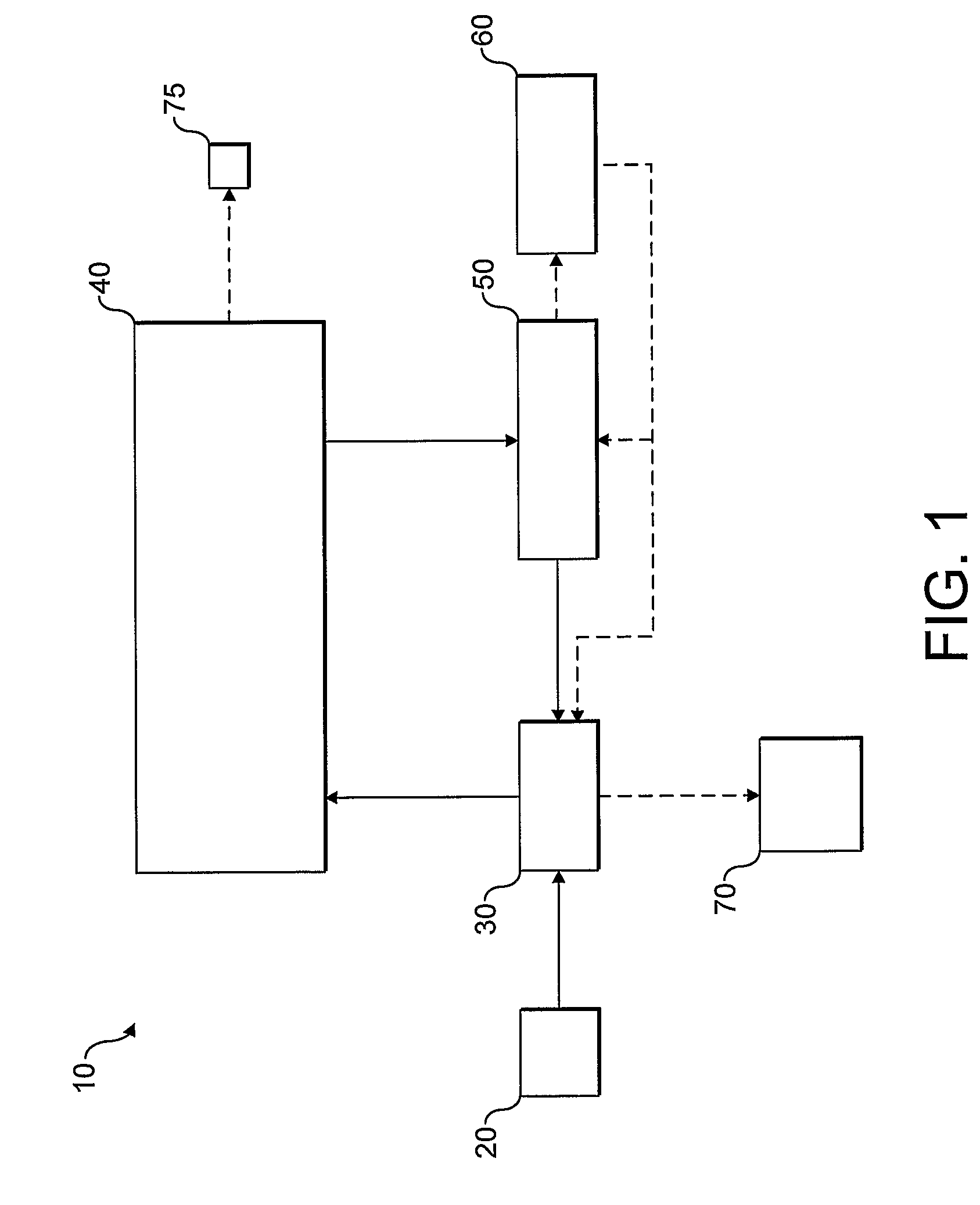
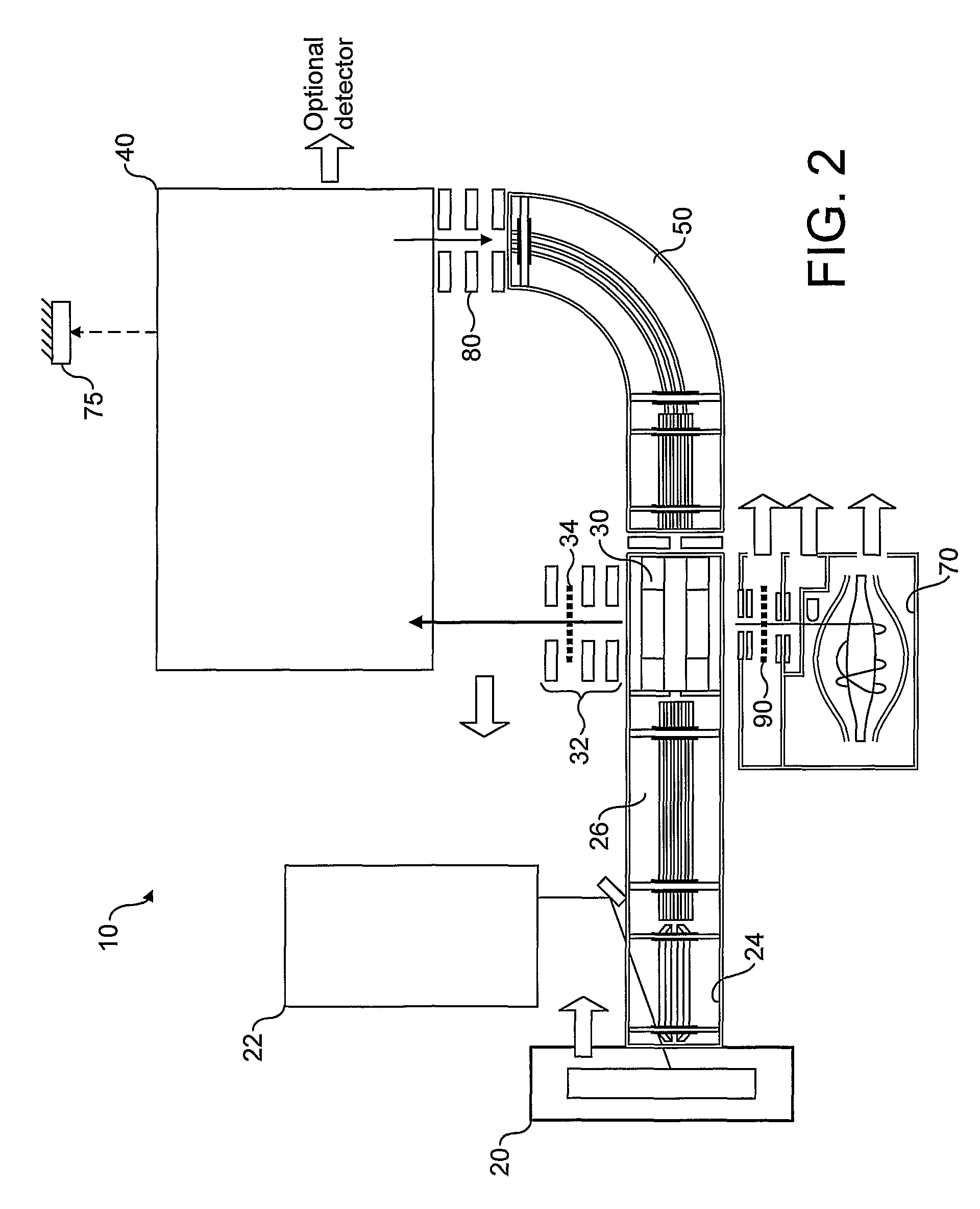
[0051]Referring first to FIG. 1, a mass spectrometer 10 is shown in block diagram format. The mass spectrometer 10 comprises an ion source 20 for generating ions to be mass analysed. The ions from the ion source 20 are admitted into an ion trap 30 which may, for example, be a gas-filled RF multipole or a curved quadrupole as is described, for example, in WO-A-05124821. The ions are stored in the ion trap 30, and collisional cooling of the ions may take place as is described for example in our co-pending application number GB0506287.2, the contents of which are incorporated herein by reference.

[0052]Ions stored in the ion trap 30 may then be pulse-ejected towards an ion selection device which is preferably an electrostatic trap 40. Pulsed ejection produces narrow ion packets. These are captured in the electrostatic trap 40 and experience multiple reflections therein in a manner to be described in connection particularly with FIG. 3 below. On each reflection, or after a certain number...


PUM


Abstract

A method for reducing the energy spread of ions over a specific and limited mass to charge ratio range is disclosed, along with an ion deceleration arrangement for implementing such a method. An electric field, having an electric field strength E is generated by a deceleration electrode arrangement (250). Ions of a specific and limited mass to charge ratio range, but having a spread of energies, are directed into the decelerating electric field generated by the deceleration electrode arrangement (250). The decelerating electric field is then removed, once substantially all of the ions of the specific mass to charge ratio range have entered the decelerating electric field. By matching the electric field strength E to the energy spread of the ions upon entry into the electric field, the energy spread of the said ions is reduced. Preferred embodiments of the invention employ energy dispersion upstream of the ion deceleration arrangement. For example, an ion mirror arrangement (200) may be used, the ions reflecting off an ion mirror (220) within that ion mirror arrangement (200) to promote energy defocusing.

Description

CROSS-REFERENCE TO RELATED APPLICATIONS[0001]This application is a National Stage application under 35 U.S.C. §371 of PCT Application No. PCT / GB2007 / 001370, filed Apr. 13, 2007, entitled “Ion Energy Spread Reduction For Mass Spectrometer”, which claims the priority benefit of GB Application No. 0607542.8, filed Apr. 13, 2006, entitled “Mass Spectrometer with Ion Storage Device”, which applications are incorporated herein by reference in their entireties.FIELD OF THE INVENTION[0002]The present invention relates to a method and an apparatus for reducing ion energy spread in a mass spectrometer or a component thereof. The invention is particularly though not exclusively applicable to the reduction of ion energy spread for ions injected into a fragmentation or collision cell.BACKGROUND TO THE INVENTION[0003]Many ion optical devices can only function well with ions having energies within a limited energy range. Examples include electrostatic lenses, in which chromatic aberrations cause d...

Claims


Application Information

Patent Timeline
Patent Type & Authority Patents(United States)
IPC IPC(8): H01J49/26H01J27/02B01D59/44
CPCH01J49/06H01J49/26H01J49/40H01J49/42
Inventor MAKAROV, ALEXANDERMONASTYRSKIY, MIKHAILGRINFIELD, DIMITRY E.
Owner THERMO FISHER SCI BREMEN
Learn More