
Disk brake

a disc brake and disc technology, applied in the direction of mechanically actuated brakes, actuators, brake types, etc., can solve the problems of increased production cost, increased production complexity, and inability to meet the requirements of the sealing function, so as to reduce production cost, simplify the assembly, and reduce the complexity of components

Inactive Publication Date: 2010-12-28
CONTINENTAL TEVES AG & CO OHG
View PDF10 Cites 0 Cited by
  • Summary
  • Abstract
  • Description
  • Claims
  • Application Information

AI Technical Summary

Benefits of technology

The invention relates to a sealing device for a shaft, which has a sealing surface and an actuating element that are integrated in design. This reduces production costs and simplifies assembly. The sealing surface is fixed over the entire circumference of the actuating element to ensure optimal sealing. A stop is arranged to prevent a slot from developing between the sealing portion and the actuating element. The stop can be a tubular projection or a flank of a recess. The sealing means can have a redundant arrangement of two sealing portions or an indented circumferential groove to improve seal-tightness and increase the useful life. The stops can be made by non-cutting manufacturing processes, such as stamping or pressing.

Problems solved by technology

In particular the axial movement impairs the sealing function because it causes a radial movement between sealing portion and sealing surface.
It is especially disadvantageous that additional effort is needed for the manufacture and assembly of actuating element and sleeve, because the complexity of production and production costs are increased as a result.

Method used


Image

  • Disk brake
  • Disk brake
  • Disk brake

Examples


first embodiment

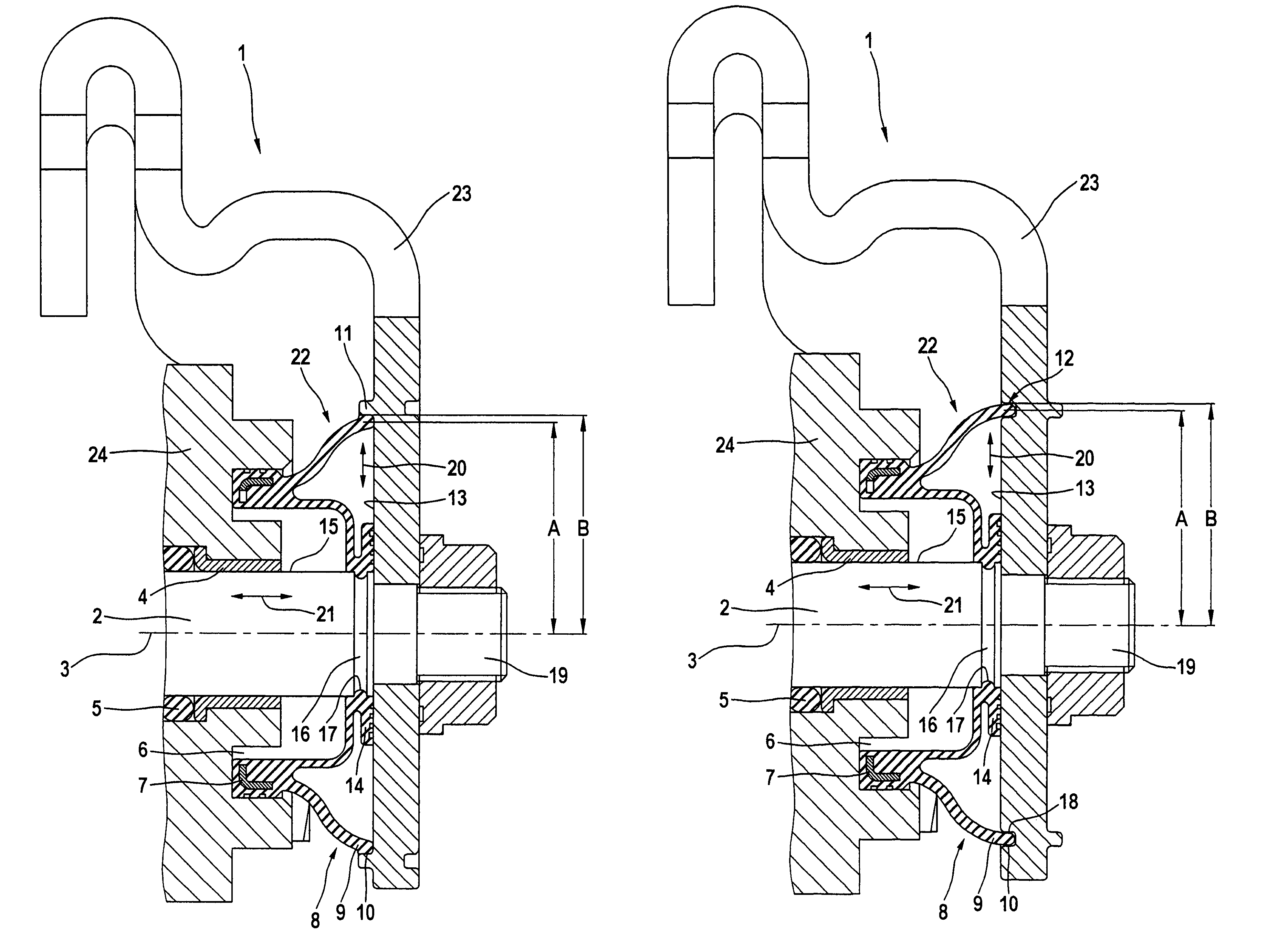
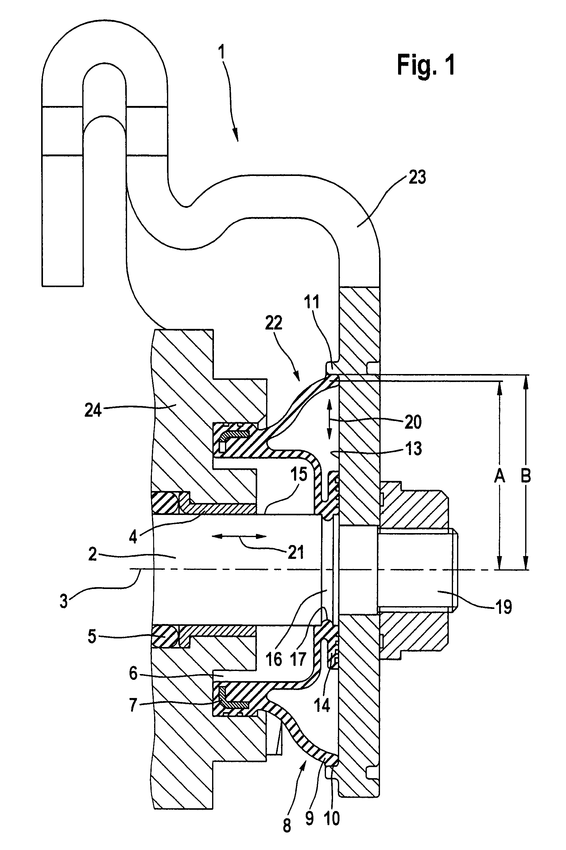
[0020]FIG. 1 further shows the disc brake 1 of the invention with a sealing means 22. It mainly comprises two sealing portions 8, 14, an axial sealing surface 13 at the actuating element 23, and a radial sealing surface 15 on the shaft 2. The sealing means 22 annularly encloses the shaft 2 and is rotatably arranged in a housing groove 6. A clamping element 7 is provided in the sealing means 22, clamping the sealing means 22 in the housing groove 6. The sealing portion 14 shuts off and seals a slot between the housing 1 and the shaft 2, with the sealing portion 14 bearing against the sealing surface 15 of the shaft 2 and being arrested by a stop 17 in an axial direction. According to this embodiment, the stop 17 is formed of a circumferential groove 16 in the shaft 2. Shaft steps or other projections on the shaft, acting as axially fixing stops, are also feasible. In order to further improve the sealing effect of the sealing portion 14, the latter also bears against the axial sealing...

second embodiment

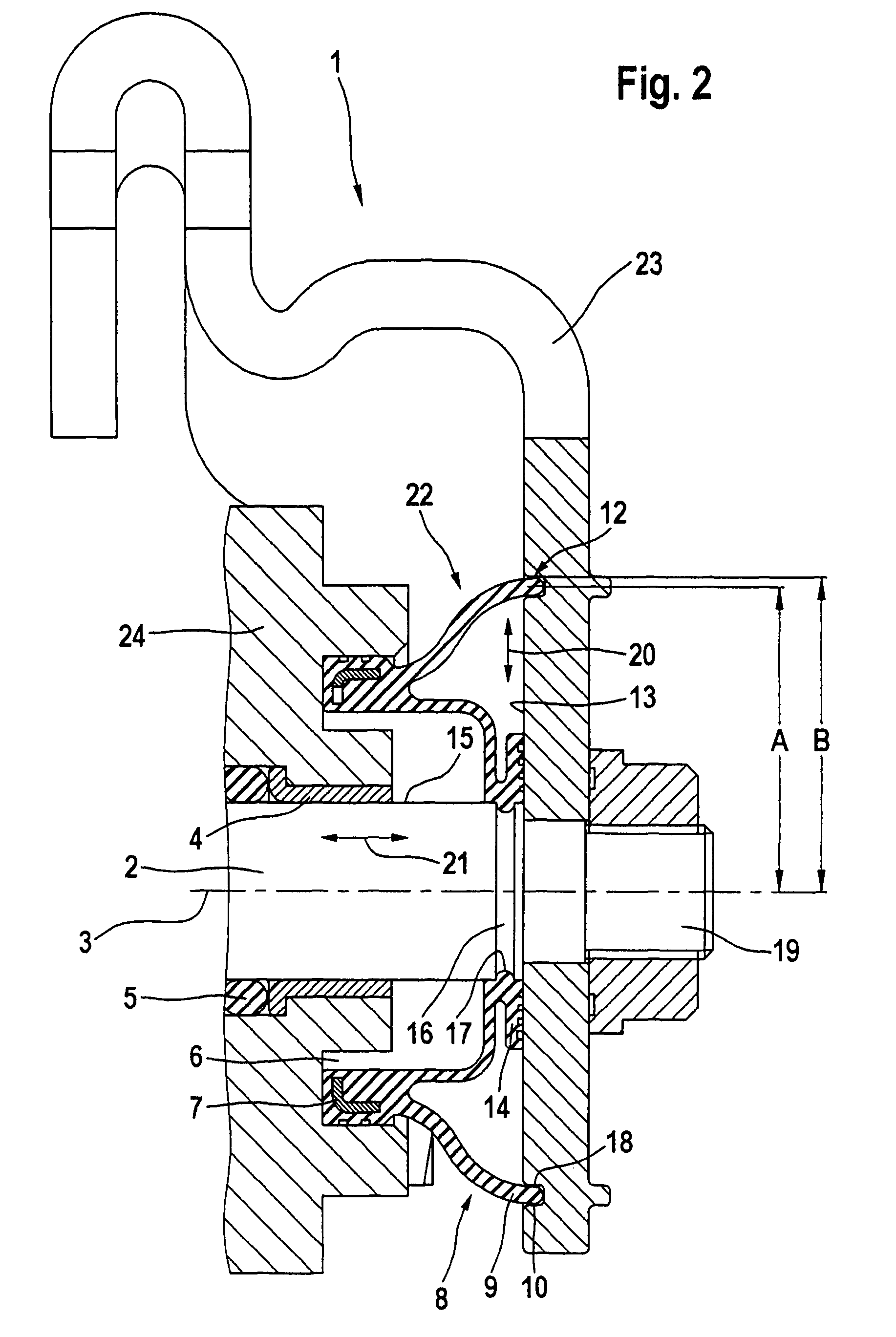
[0026]A second embodiment is explained in connection with FIG. 2. As the basic design of both embodiments is identical, only the differences will be dealt with in the following. The differences can be seen in that the stop 10 is not formed by a projection 11 (FIG. 1), but by a flank of a recess 12. To make this recess 12, non-cutting processes such as stamping or pressing can be used, which are principally less cost-intensive than cutting shaping processes.

[0027]To explain the mode of operation of the embodiment of Figure 2, reference is made to the description of FIG. 1. However, it shall be stated that the shape of the stop 10 as recess 12 has the following advantage in terms of function. As the recess 12 accommodates part of the sealing lip 9 of the sealing portion 8, a radial movement 20 on the actuating element 23 is completely ruled out, because the sealing lip abuts on both flanks of the recess 12. The flank of the recess 12 pointing away from the axis 3 assumes the function ...


PUM


Abstract

A disc brake with a rotatable and axially displaceable shaft for actuation, and with an actuating element. Further, a sealing means with a sealing portion is provided, which acts elastically on an associated sealing surface, with the sealing portion closing a slot between the sealing surface and the housing for sealing purposes and abutting on a stop. The stop, the sealing surface and the actuating element are designed integrally. This measure allows significantly reducing the production costs because the complexity of components is decreased and the assembly is thus simplified.

Description

[0001]This application is the U.S. national phase application of PCT International Application No. PCT / EP2006 / 050285, filed Jan. 18, 2006, which claims priority to German Patent Application No. DE102005002415.7, filed Jan. 18, 2005 and German Patent Application No. DE102005046805.5, filed Sep. 30, 2005, the contents of such applications being incorporated by reference herein.BACKGROUND OF THE INVENTION[0002]The present invention relates to a disc brake with a shaft for actuation, which is supported in a housing in a rotatable and axially displaceable manner and extends with one shaft end through a housing opening, with an actuating element being arranged on the shaft end. Further, a sealing means with a sealing portion is provided, which acts elastically on an associated sealing surface. In consequence of an axial movement of the shaft, the sealing portion is movable on the associated sealing surface transversely to the axial movement of the shaft, and is limited by a stop, with the...

Claims


Application Information

Patent Timeline
Patent Type & Authority Patents(United States)
IPC IPC(8): F16D55/08F16D65/28
CPCF16D65/18F16D2121/14F16D2125/64F16D65/14
Inventor PETRI, RALPH
Owner CONTINENTAL TEVES AG & CO OHG
Learn More