
Method and system for a multiple output capacitive buck/boost converter

a technology of capacitive buck and boom converter, applied in the field of integrated circuit power control, can solve problems such as excessive leakage, degrade performance, and drive gate voltage drop

Active Publication Date: 2010-12-14
AVAGO TECH INT SALES PTE LTD
View PDF3 Cites 13 Cited by
  • Summary
  • Abstract
  • Description
  • Claims
  • Application Information

AI Technical Summary

Problems solved by technology

Furthermore, as device sizes continue to shrink for higher speed and lower power consumption, a high voltage may degrade performance and cause excessive leakage.
With thinner gate oxides, gate leakage current may become significant using historical bias voltages, thus driving gate voltages lower.
However, if a transmitter / receiver may be integrated in the same device, a higher bias voltage may also be required.
However, there may be noise in the bias voltage, which may be mitigated by capacitive filters.

Method used


Image

  • Method and system for a multiple output capacitive buck/boost converter
  • Method and system for a multiple output capacitive buck/boost converter
  • Method and system for a multiple output capacitive buck/boost converter

Examples


Embodiment Construction

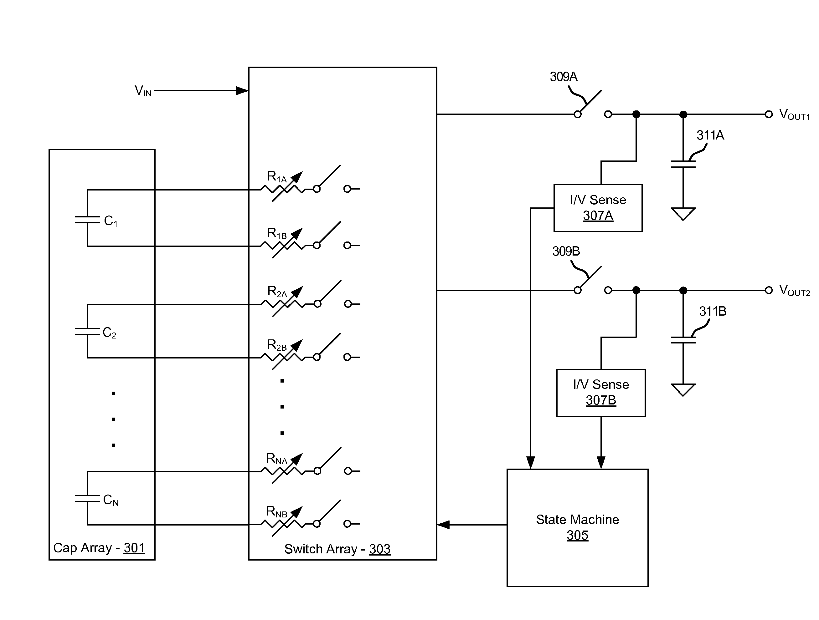
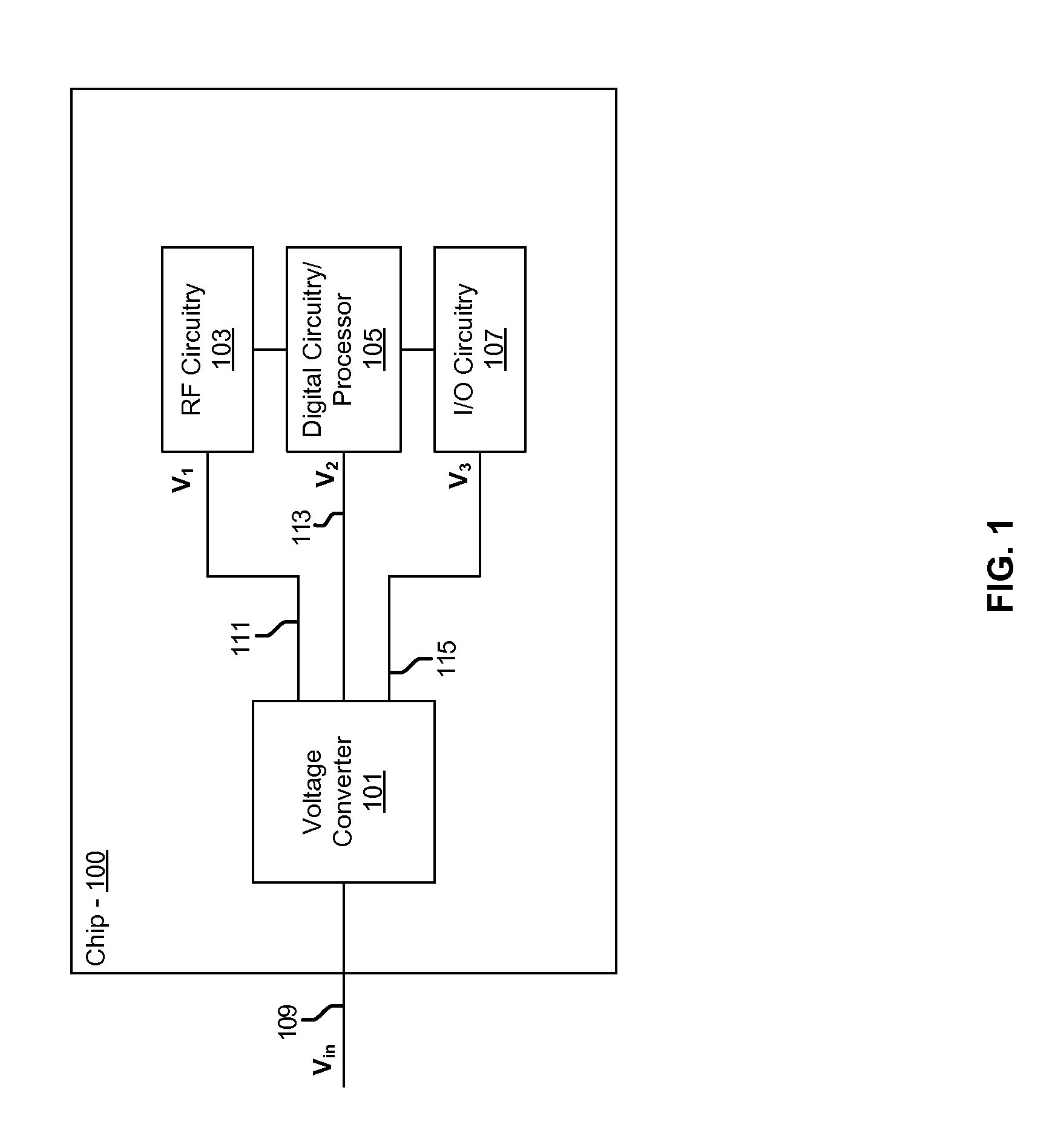
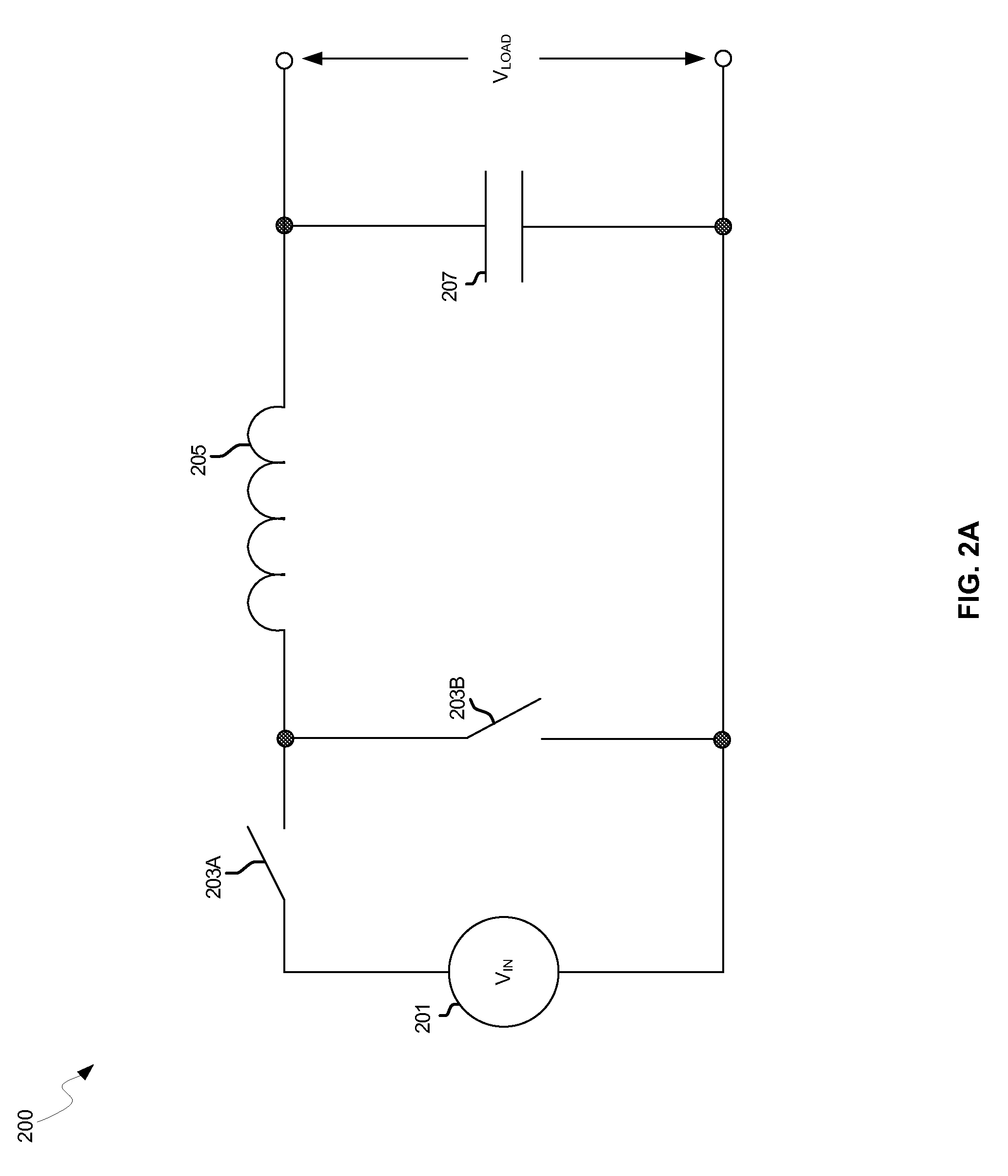
[0017]Certain aspects of the invention may be found in a method and system for a multiple output capacitive buck / boost converter. Exemplary aspects of the invention may comprise charging one or more input capacitors via an input voltage. One or more output voltages may be generated on a chip by switching one or more of the charged input capacitors to one or more output capacitors via a switch array on the chip. The switch array may be controlled, for example, via a state machine. A constant current may be generated for the one or more output voltages via one or more current comparators and / or a constant voltage may be generated for the one or more output voltages via one or more voltage comparators. A variable resistance may be coupled in series with one or more switches in the switch array. The one or more input capacitors may be discrete capacitors external to the chip or integrated within the chip. One or more of the output voltages may be greater than the input voltage, or may b...


PUM


Abstract

Methods and systems for a multiple output capacitive buck / boost converter are disclosed and may include charging one or more input capacitors via an input voltage. One or more output voltages may be generated on a chip by switching the charged input capacitors to output capacitors via a switch array on the chip. The switch array may be controlled via a state machine. A constant current and / or voltage may be generated for the one or more output voltages via one or more current and / or voltage comparators. A variable resistance may be coupled in series with one or more switches in the switch array. The one or more input capacitors may be discrete capacitors external to the chip and / or integrated within the chip. One or more of the output voltages may be greater than the input voltage, or may be less than the input voltage.

Description

CROSS-REFERENCE TO RELATED APPLICATIONS / INCORPORATION BY REFERENCE[0001][Not Applicable]FEDERALLY SPONSORED RESEARCH OR DEVELOPMENT[0002][Not Applicable]MICROFICHE / COPYRIGHT REFERENCE[0003][Not Applicable]FIELD OF THE INVENTION[0004]Certain embodiments of the invention relate to integrated circuit power control. More specifically, certain embodiments of the invention relate to a method and system for a multiple output capacitive buck / boost converter.BACKGROUND OF THE INVENTION[0005]Electronic circuits typically require a bias voltage for proper operation. The voltage level required by a circuit depends on the application. A circuit for transmitting electromagnetic radiation may require a higher voltage than a circuit used for processing data. The optimum voltage may be determined by the bias voltage requirements of the transistors, or other active devices, within the circuit.[0006]A bipolar transistor circuit may require a higher voltage in amplifier applications to avoid saturation...

Claims


Application Information

Patent Timeline
Patent Type & Authority Patents(United States)
IPC IPC(8): H02J1/10H02J3/38H02J7/34
CPCH02M3/1582H02M2001/009H02M1/009
Inventor WALLEY, JOHN
Owner AVAGO TECH INT SALES PTE LTD
Learn More