
Disk braking device and motorcycle provided with the disk braking device

a technology of disc brakes and braking devices, which is applied in the direction of fluid actuated brakes, cycle equipment, cycle brakes, etc., can solve the problems of decreasing radiation quality, and achieve the effect of improving heat radiation quality and reducing friction member abrasion

Active Publication Date: 2010-12-14
YAMAHA MOTOR CO LTD
View PDF21 Cites 5 Cited by
  • Summary
  • Abstract
  • Description
  • Claims
  • Application Information

AI Technical Summary

Benefits of technology

The solution increases heat radiation quality and decreases friction member abrasion by providing a continuous heat conduction path and efficient heat discharge, while also facilitating the removal of debris and reducing brake noise.

Problems solved by technology

This is in contrast to the prior art, where multiple through-holes are aligned on a radial line and interrupt the heat conduction path, thereby decreasing radiation quality.

Method used


Image

  • Disk braking device and motorcycle provided with the disk braking device
  • Disk braking device and motorcycle provided with the disk braking device
  • Disk braking device and motorcycle provided with the disk braking device

Examples


Embodiment Construction

[0016]An embodiment of the invention will be described below with reference to the accompanying drawings.

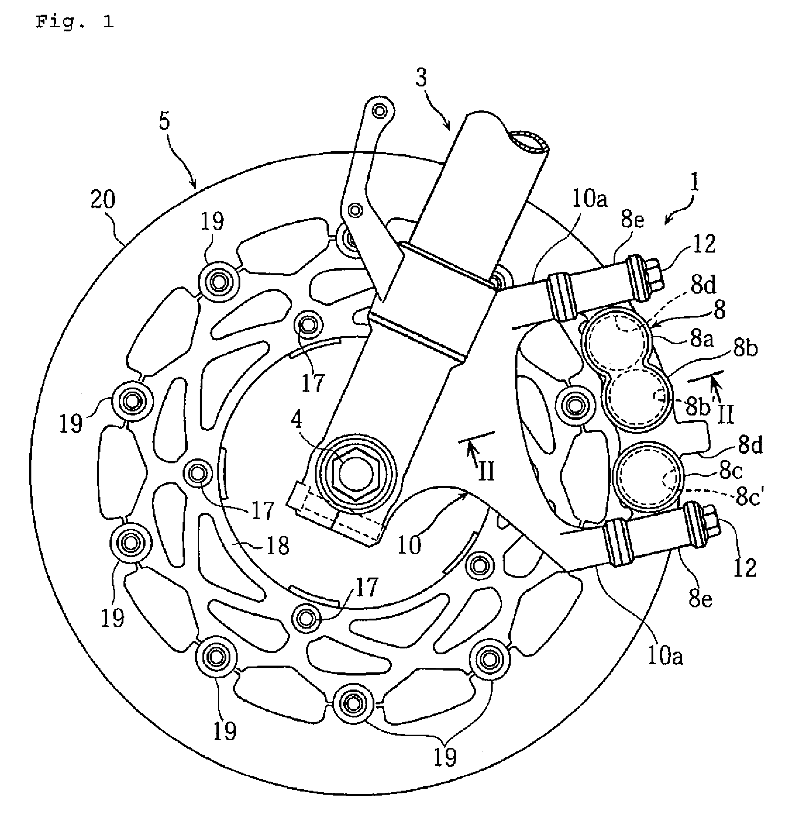
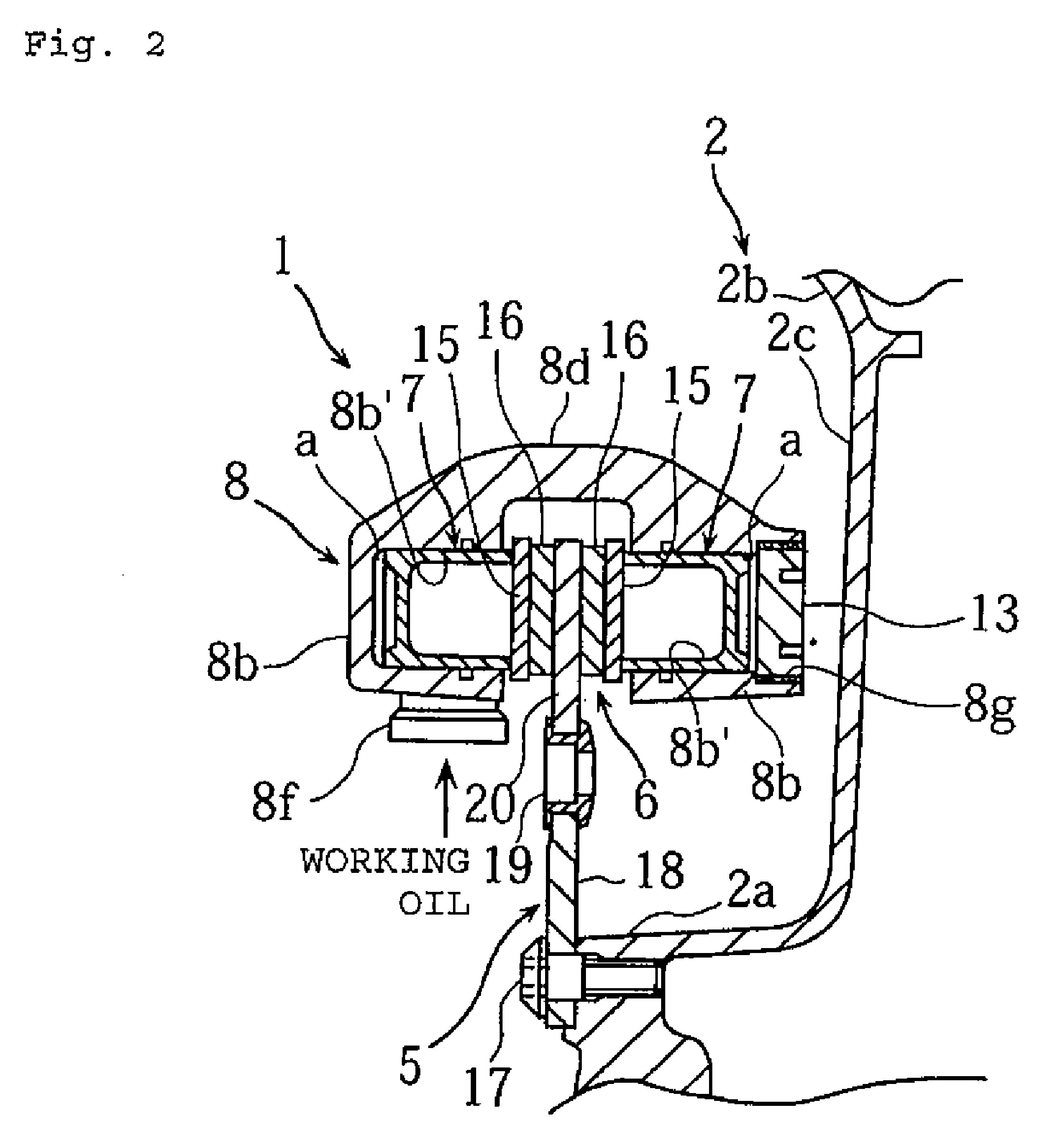
[0017]FIGS. 1-4 illustrate a disk braking device according to an embodiment of the invention. The illustrated embodiment is a disk braking device for motorcycles.

[0018]In the drawings, the reference numeral 1 denotes a front disk braking device arranged on a front wheel 2 of a motorcycle. The front wheel 2 is journaled by a lower end of a front fork 3. The front fork 3 is supported on a head pipe, which is fixed to a front end of a vehicle body frame (not shown), to be steered left and right, and a steering handle (not shown) is mounted to an upper end of the front fork 3.

[0019]The front wheel 2 is constructed such that a hub 2a and a rim 2b with a tire (not shown) mounted thereto are connected to each other by a plurality of spokes, and an axle shaft 4 is inserted into the hub 2a with a bearing (not shown) therebetween and is fixed to the front fork 3.

[0020]A rearwardly projecti...


PUM


Abstract

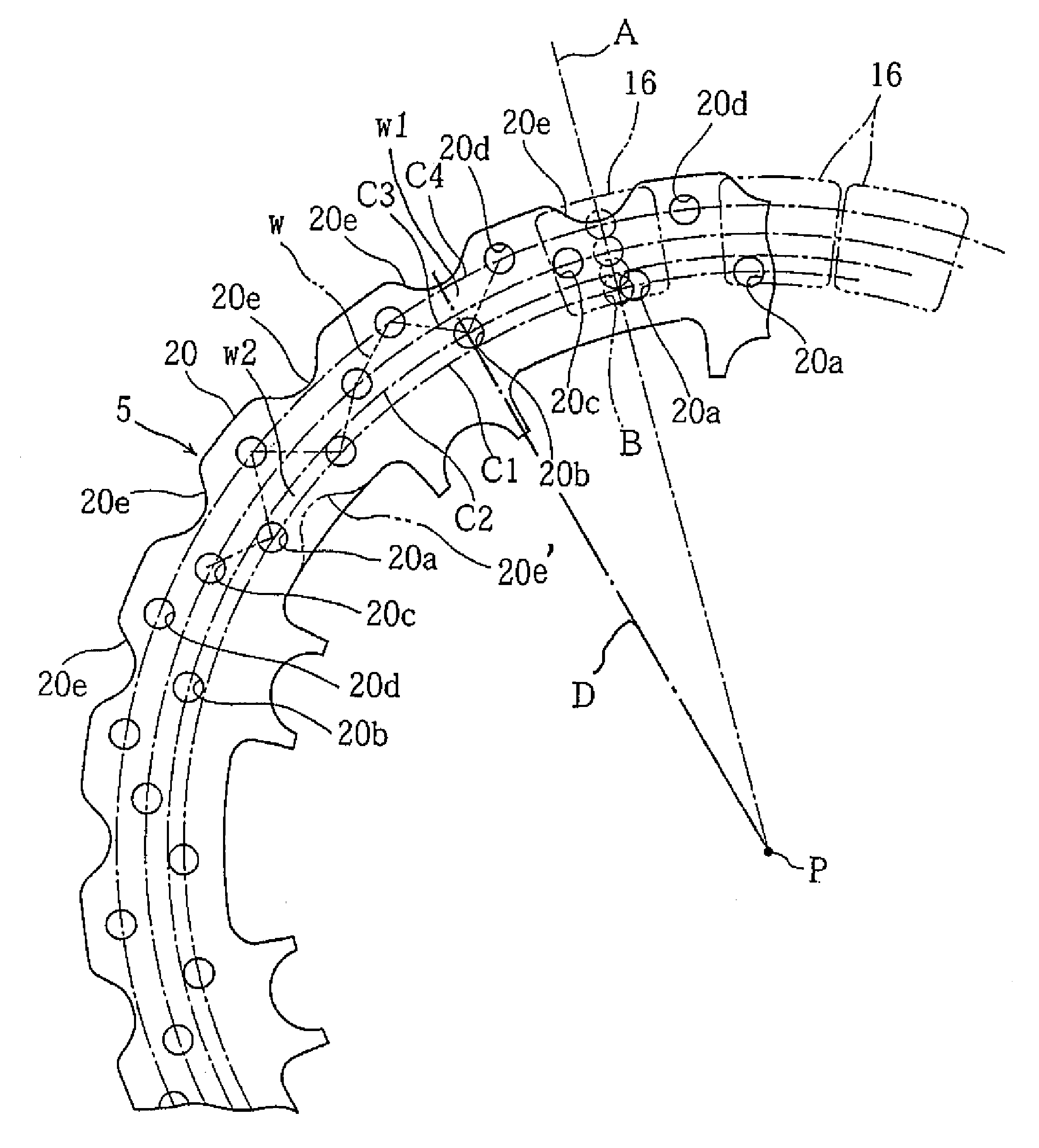
A disk braking device for a motorcycle ensures radiation quality of a disk plate and reduces friction member abrasion of a friction member. A plurality of through-holes are formed in the disk plate and a plurality of notches are formed at peripheral edges of the disk plate. The through-holes are arranged so that one of the through-holes or less is disposed on a radial line extending from the center of the disk plate.

Description

RELATED APPLICATIONS[0001]This application claims the benefit of priority under 35 USC 119 of Japanese patent application No. 2005-249313, filed on Aug. 30, 2005, which application is hereby incorporated by reference in its entirety.BACKGROUND OF THE INVENTION[0002]1. Field of the Invention[0003]The present invention relates to a disk braking device in which a disk plate fixed to a wheel is interposed by friction members, and a motorcycle provided with the disk braking device.[0004]2. Description of Related Art[0005]In some disk braking devices for motorcycles there are a multiplicity of “lightening” holes formed at circumferential intervals on the disk plate in order to decrease the weight of the disk plate. In addition, recesses are sometimes formed at circumferential intervals at an outer edge of the disk plate in order to suppress brake noise (see, for example, WO 2004 / 042247).[0006]In such disk plates, the lightening holes are typically arranged in a radially aligned and parall...

Claims


Application Information

Patent Timeline
Patent Type & Authority Patents(United States)
IPC IPC(8): F16D65/12F16D65/18
CPCF16D65/12F16D2065/026F16D2065/1316F16D2065/1356F16D2069/004
Inventor KAWAI, HIDEOABE, MANABUMIGITA, ITSUROUURA, KAZUAKIKURITA, MASATOSHIIKKI, FUJIO
Owner YAMAHA MOTOR CO LTD
Learn More