High-frequency receiver and adjacent interference wave reducing method

a technology of interference wave and receiver, which is applied in the field of high-frequency receiver and a method of reducing adjacent interference wave, can solve problems such as deteriorating reception sensitivity, and achieve the effect of optimizing reception level and improving reception quality

Inactive Publication Date: 2010-12-07
PIONEER CORP
View PDF15 Cites 2 Cited by
  • Summary
  • Abstract
  • Description
  • Claims
  • Application Information

AI Technical Summary

Benefits of technology

[0010]Another aspect of the invention provides a method of alleviating an influence of adjacent interference waves in a high-frequency receiver used in a location where an identical set of broadcast channels can be received with different broadcast waves which are broadcast or relayed in frequency bands different from one another. The method comprises separating received broadcast channel signals into I signals and Q signals; passing the I signals and Q signals to a pair of variable LPFs which pass only frequency components of the I signals and Q signals which components are within respective bandwidths thereof, each variable LPF being configured to be capable of changing the bandwidth thereof in response to a control signal given externally; for each of the different broadcast waves, demodulating the I and Q signals derived from the broadcast wave into a demodulated signal; selecting one of the demodulated signals which has a better reception quality; detecting a reception level of each of the received broadcast waves; detecting noise evaluation information of each of the received broadcast waves; and based on the reception level and the noise evaluation information for a selected demodulated signal selected by the selector, supplying the pair of variable LPFs with the control signal which controls the bandwidths of the variable LPFs so as to optimize the reception level and the noise evaluation information for the selected demodulated signal.

Problems solved by technology

When there are broadcast waves adjacent to a broadcast wave intended to be received, it is likely that the adjacent broadcast waves (hereinafter referred to as “adjacent interference waves” as well) interfere with the broadcast wave intended to be received and a reception failure is caused to deteriorate sensitivity of reception.

Method used


Image

  • High-frequency receiver and adjacent interference wave reducing method
  • High-frequency receiver and adjacent interference wave reducing method
  • High-frequency receiver and adjacent interference wave reducing method

Examples


Embodiment Construction

[0040]Exemplary embodiments of a high-frequency receiver and a method of reducing adjacent interference waves according to the present invention are explained in detail below with reference to the accompanying drawings. The present invention is not limited by the embodiments. All combinations of characteristics explained in the embodiments are not always necessary for the means for solving the problems according to the present invention. Components in the embodiments include components that those skilled in the art can easily anticipate or components substantially the same as the components.

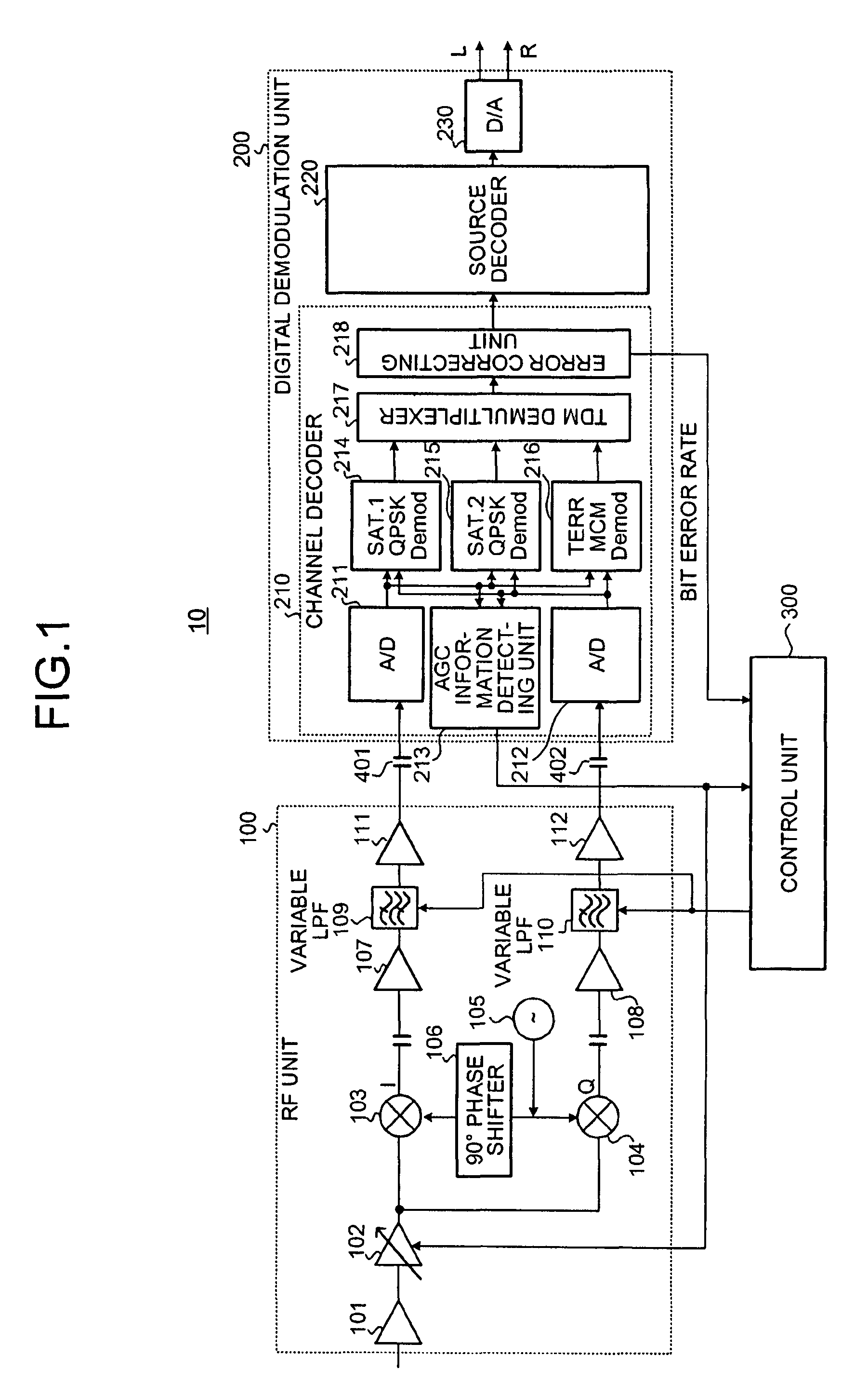
[0041]FIG. 1 is a diagram of a structure of a high-frequency receiver 10 according to an embodiment of the present invention. The high-frequency receiver 10 shown in FIG. 1 indicates, in particular, a digital broadcast receiver that receives the XM satellite radio broadcast.

[0042]The high-frequency receiver 10 shown in FIG. 1 adopts a direct conversion system (also referred to as “zero IF system”...


PUM


Abstract

A high-frequency receiver alleviates an influence of adjacent interference waves in a location where an identical set of broadcast channels can be received with different broadcast waves which are broadcast or relayed in frequency bands different from one another by satellites and ground repeater(s). The I and Q signals are passed to a pair of variable LPFs. A demodulation unit is provided for each of said different broadcast waves to demodulate the I and Q signals derived from the broadcast wave into a demodulated signal. One of the demodulated signals which has a better reception quality is selected for output. Based on a reception level and a noise evaluation information (e.g., the bit error rate) for a selected demodulated signal, a controller controls the bandwidths of the variable LPFs so as to optimize the reception level and the noise evaluation information for the selected demodulated signal.

Description

TECHNICAL FIELD[0001]The present invention relates to a high-frequency receiver and a method of reducing adjacent interference waves. More particularly, the present invention relates to a high-frequency receiver capable of reducing adjacent interference waves and a method of reducing adjacent interference waves.BACKGROUND ART[0002]In North America, the XM satellite radio broadcast has been conducted since 2001. FIG. 5 is a diagram for explaining an XM satellite radio broadcast system. As shown in FIG. 5, in the XM satellite radio broadcast, the same contents are transmitted by satellite waves SAT1 and SAT2 from two satellites 1 and 2 and a ground wave TERR from a ground repeater. If a receiver can receive at least one of the waves, the receiver can reproduce sound without sound interruption. The satellite waves SAT1 and SAT2 are QPSK-modulated and the ground wave TERR is MCM-modulated.[0003]FIG. 6 is a diagram of a frequency band of the XM satellite radio broadcast. The XM satellite...

Claims


Application Information

Patent Timeline
Patent Type & Authority Patents(United States)
IPC IPC(8): H04B1/00
CPCH04B1/1027H04H40/90H04H60/12H04B2001/1045H04H20/06H04H20/22
Inventor KATO, SEI
Owner PIONEER CORP
Why Eureka
Try Eureka