
Method of driving organic light emitting display

a technology of organic light and display, applied in the direction of instruments, static indicating devices, etc., can solve the problems of image sticking, image sticking, and the disadvantage of displaying the image in full color even during a standby mode, and achieve the effect of increasing the duty ratio of emission control signals and adjusting luminan

Active Publication Date: 2010-11-23
SAMSUNG DISPLAY CO LTD
View PDF35 Cites 1 Cited by
  • Summary
  • Abstract
  • Description
  • Claims
  • Application Information

AI Technical Summary

Benefits of technology

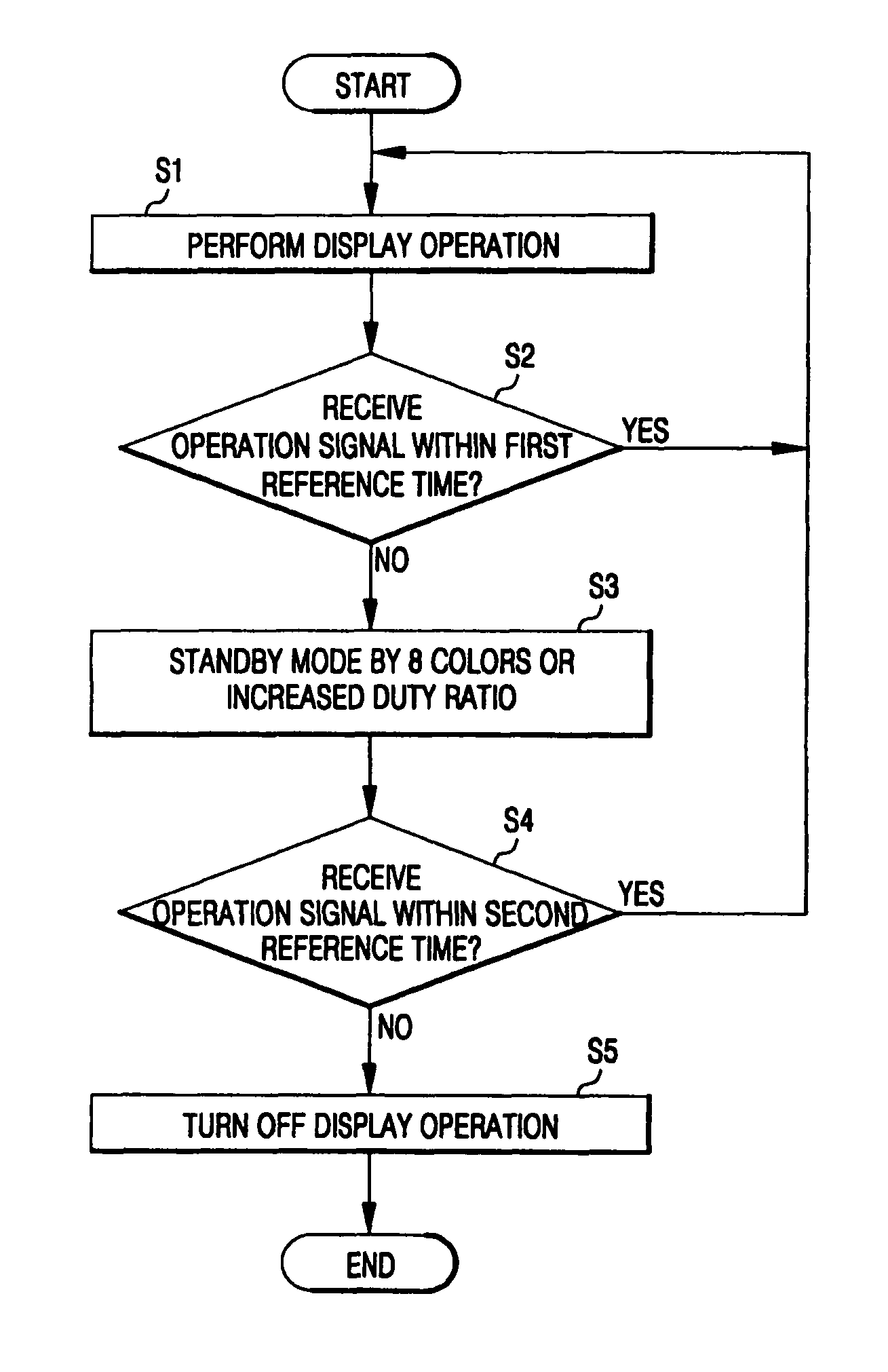
The present invention provides a method for driving an organic light emitting display that adjusts luminance by restricting a plurality of pixels to 8 colors or increasing a duty ratio of the emission control signals. This method includes receiving a data signal, determining whether the pixels receive an operation signal within a first reference time, and switching to a standby mode in which the pixels are displayed in restricted colors or a duty ratio of the emission control signals is adjusted to reduce luminance, when the operation signal is not received within the first reference time. The technical effect of this invention is to improve the display's energy efficiency and reduce its power consumption while maintaining its brightness and clarity.

Problems solved by technology

However, the conventional organic light emitting displays have certain disadvantages that are discussed below.
The conventional methods of driving the organic light emitting display have the disadvantage of displaying the image in full color even during a standby mode.
As a result, image sticking occurs and life span is reduced due to high power consumption and degradation.

Method used


Image

  • Method of driving organic light emitting display
  • Method of driving organic light emitting display
  • Method of driving organic light emitting display

Examples


Embodiment Construction

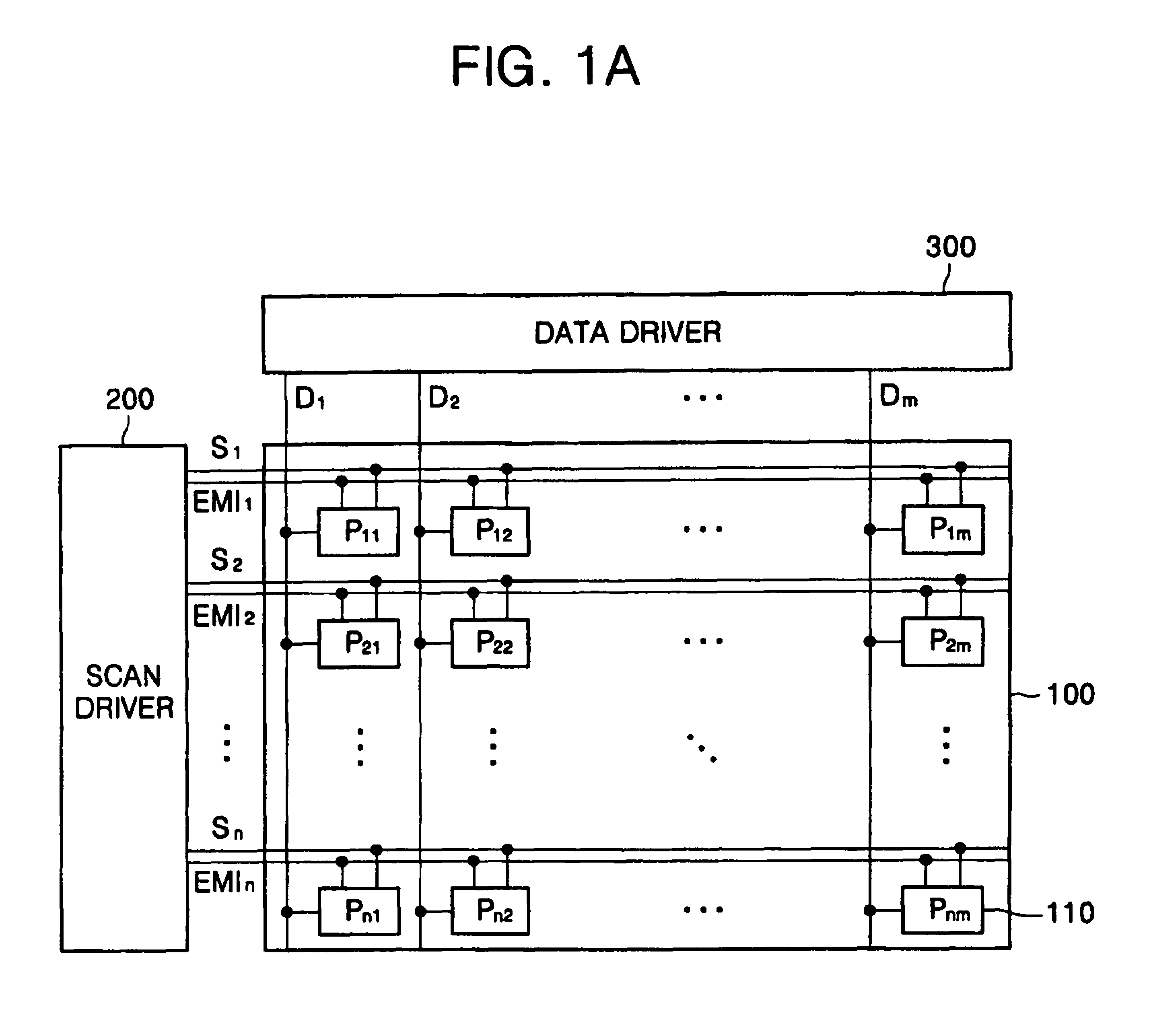
[0018]FIG. 1A is a schematic diagram of an organic light emitting display according to an exemplary embodiment of the present invention. The organic light emitting display includes a display panel 100, a scan driver 200 and a data driver 300.

[0019]The display panel 100 includes a plurality of data lines D1 to Dm arranged in a first direction, a plurality of scan lines S1 to Sn arranged in a second direction transverse to the first direction, a plurality of emission control lines EMI1 to EMIn arranged in the second direction, and a plurality of pixels 110 that include pixel circuits P11 to Pnm. Each pixel 110 is formed in a pixel region which is defined by an intersection of the plurality of data lines D1 to Dm, the plurality of scan lines S1 to Sn, and the plurality of emission control lines EMI1 to EMIn.

[0020]The scan driver 200 is coupled to the plurality of scan lines S1 to Sn and the plurality of emission control lines EMI1 to EMIn. The scan driver 200 applies scan signals for s...


PUM


Abstract

A method of driving an organic light emitting display is provided in which, during a standby mode, a display operation is performed using only eight colors. In the alternative, the luminance of a plurality of pixels is reduced by adjusting a duty ratio of the emission control signals. By reducing the luminance, power consumption and image sticking are reduced, and the life span of the pixels is increased.

Description

CROSS-REFERENCE TO RELATED APPLICATION[0001]This application claims priority to and the benefit of Korean Patent Application No. 2005-36418, filed on Apr. 29, 2005, the entire content of which is incorporated herein by reference.BACKGROUND OF THE INVENTION[0002]1. Field of the Invention[0003]The present invention relates to a method of driving an organic light emitting display and, more particularly, to a method of driving an organic light emitting display which adjusts luminance during a standby mode by restricting a plurality of pixels to 8 colors.[0004]2. Description of Related Art[0005]Organic light emitting displays have been used in cellular phones, digital cameras, home electronics, and similar devices as an alternative to a liquid crystal display (LCD) because of their fast response time, high contrast ratio, wide viewing angle, and low power consumption. Further, organic light emitting displays attract attention as the next generation flat panel display due to their excelle...

Claims


Application Information

Patent Timeline
Patent Type & Authority Patents(United States)
IPC IPC(8): G09G3/30
CPCG09G3/3233G09G3/2014G09G2300/0842G09G2300/0861G09G2330/022G09G2340/0428G09G3/30
Inventor LEE, JAE-SUNG
Owner SAMSUNG DISPLAY CO LTD
Learn More