
Adhesive segment indexing method and apparatus and roll of adhesive segments for use therewith

a technology of indexing method and adhesive segment, which is applied in the direction of film/foil adhesives without carriers, mechanical control devices, instruments, etc., can solve the problems of difficult, unsafe, inefficient and inconvenient use of “glue gun” equipment, and achieve the effect of facilitating the assured release of adhesive segmen

Inactive Publication Date: 2010-11-23
GLUE DOTS INT
View PDF125 Cites 4 Cited by
  • Summary
  • Abstract
  • Description
  • Claims
  • Application Information

AI Technical Summary

Benefits of technology

"The present invention provides an automated system and method for applying thermoplastic adhesives to work pieces using a roll of adhesive segments. The system includes an applicator head that pushes the adhesive segment against the work piece to apply it. The adhesive segment-laden carrier release tape has optically detectable index markings that allow for accurate positioning of the adhesive segment during application. The system also includes components such as a supply spool, tape guide, take-up spool, and tape clamp. The invention provides a more efficient and reliable method for applying adhesives to work pieces."

Problems solved by technology

Using a “glue gun” device is an inefficient, difficult, and at times unsafe method of applying thermoplastic adhesives to a desired surface.
First, the cost of using this equipment is relatively high.
The apparatus and method are also inefficient consumers of both energy and glue.
Specifically, the costs of the operation of such a dispenser (electrical usage, wasted glue from droppings) for only short periods of time outweigh any other potential advantages which may be realized.
Safety is also an issue.
Glue-gun devices are potentially unsafe because they include a heat source to heat a quantifiable supply of adhesive material to its melting point.
A major drawback of using such an instrument is that the hot, molten thermoplastic adhesive can burn untrained users, and can also melt the substrate the user is applying the glue to.
Finally, application of thermoplastic adhesives from a glue-gun does not enable the thermoplastic adhesive to withstand cold temperatures or to cool to a smooth surface, but instead will typically leave “spider webs” in the dried adhesive.
In short, glue-gun applicators of the prior art are inefficient, difficult, and unsafe.
Although the adhesive segment-laden carrier release tape taught in the '670 patent provides a highly innovative and commercially successful product, application of the adhesive segments from the release tape onto a work piece in an efficient manner remains a challenge.
Advancing the carrier release tape manually in this manner is time-consuming, and the “spent” carrier release tape must be either torn off and disposed of or left intact and in the way.
Finally, dropping or unintentional uncoiling of the unused roll of adhesive segment-laden carrier release tape may also be a problem.
While such an embodiment remedies the '670 patent's problem of having a length of uncut spent carrier release tape, the carrier release tape of the '442 patent (as well as of the '670 patent) does not lend itself to use in combination with a more efficient dispenser for application of the adhesive segments.
This application process exposes unspent adhesive segments to dust and other debris, which may cause the adhesive segments to lose their adhesive tack and damage or soil the desired surface.
Not all previously known devices for applying thermoplastic adhesive from adhesive segment-laden carrier release tapes are entirely manual in operation.
A limitation of previous systems and methods for applying thermoplastic adhesives to a work piece from an adhesive segment-laden carrier release tape is that operation of such systems and methods actually to apply the thermoplastic adhesive to a work piece is essentially manual.
Such systems and methods for applying thermoplastic adhesives to work pieces from an adhesive segment-laden carrier release tape are thus not well suited to high speed high volume applications.

Method used


Image

  • Adhesive segment indexing method and apparatus and roll of adhesive segments for use therewith
  • Adhesive segment indexing method and apparatus and roll of adhesive segments for use therewith
  • Adhesive segment indexing method and apparatus and roll of adhesive segments for use therewith

Examples


Embodiment Construction

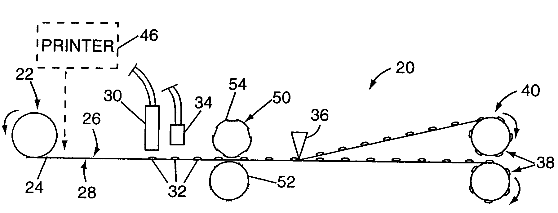
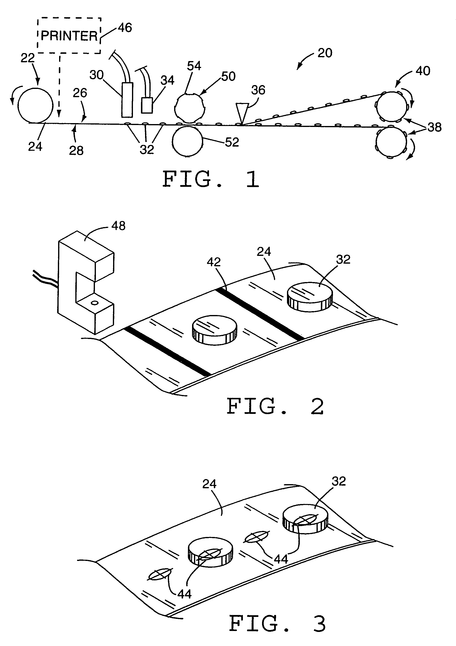
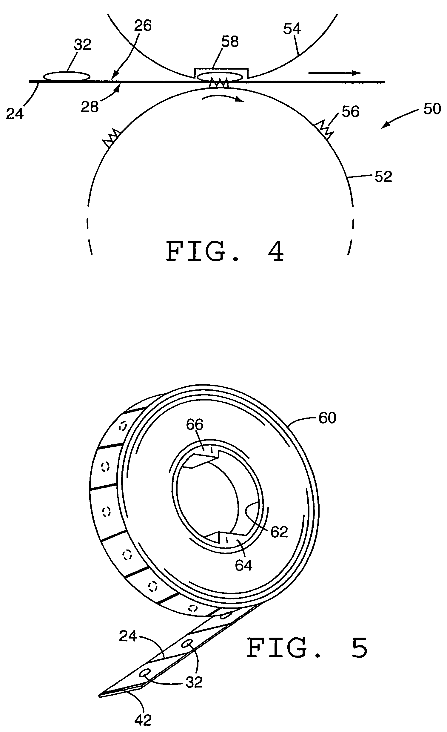
[0036]The present invention provides a system and method for applying automatically adhesive segments from an adhesive segment-laden carrier release tape onto a work piece or series of work pieces, in a rapid and effective manner. The present invention may employ optical index markings on the carrier release tape to assure accurate positioning of the carrier release tape within the apparatus. The system also employs an automatic applicator method that ensures full and sure release of adhesive segments from the carrier release tape onto a work piece during the application process. Both the structure and operation of an exemplary applicator apparatus and method in accordance with the present invention, as well as the optically indexed carrier release tape used therein, and the manufacturer of such an adhesive segment-laden carrier release tape will now be described in detail herein.

[0037]An exemplary process for manufacturing an adhesive segment-laden carrier release tape for use with...


PUM

PropertyMeasurementUnit
flexibleaaaaaaaaaa
distanceaaaaaaaaaa
opticalaaaaaaaaaa

Abstract

An automated system and method for applying thermoplastic adhesives to work pieces from a roll of adhesive segments applied to an adhesive segment-laden carrier release tape. The present invention may be implemented in a system that automatically advances the adhesive segment-laden carrier release tape to position an adhesive segment thereon in the apparatus for application thereof to a work piece. Accurate indexing and advancement of the adhesive segment-laden carrier release tape preferably is provided by optical indexing of the carrier release tape, e.g., by the optical detection of a transverse line or other index marking printed or otherwise provided on the adhesive segment carrier release along with the adhesive segments deposited thereon.

Description

[0001]This patent application is a continuation-in-part of U.S. patent application Ser. No. 10 / 360,457, filed on Feb. 8, 2003, now abandoned and is also a continuation-in-part of U.S. patent application Ser. No. 10 / 360,395, also filed on Feb. 8, 2003, now U.S. Pat. No. 7,195,049 both of which are continuations-in-part of U.S. patent application Ser. No. 10 / 125,012, filed on Apr. 18, 2002, now U.S. Pat. No. 6,686,016, and continuations-in-part of U.S. patent application Ser. No. 09 / 998,950, filed on Nov. 15, 2001, now U.S. Pat. No. 6,640,864, both of which are continuations of U.S. patent application Ser. No. 09 / 363,200, filed on Jul. 29, 1999, now U.S. Pat. No. 6,319,442, which is in turn a continuation-in-part of U.S. patent application Ser. No. 08 / 909,189, filed on Aug. 11, 1997, now U.S. Pat. No. 5,935,670, which in turn claims the benefit of U.S. Provisional Patent Application No. 60 / 036,896, filed on Feb. 6, 1997.FIELD OF THE INVENTION[0002]The present invention pertains genera...

Claims


Application Information

Patent Timeline
Patent Type & Authority Patents(United States)
IPC IPC(8): B32B41/00B32B9/00B65H37/00B65H37/02C09J7/10
CPCB65H37/002B65H37/02C09J7/00C09J7/0232B65H2511/512B65H2701/124B65H2701/1241Y10T428/1495B65H2701/19402C09J2201/28Y10T428/1476B65H2701/194C09J7/403C09J7/10C09J2301/204
Inventor DOWNS, JOHN P.PETERSON, BURTON J.THIEDE, RICHARD A.
Owner GLUE DOTS INT
Learn More