
Transaction card

a technology of transaction cards and cards, applied in the field of transaction cards, can solve the problems of increasing administrative and security problems, such as fraud, merchant settlement, merchant settlement, etc., and increasing the number of transactions

Inactive Publication Date: 2010-11-23
LIBERTY PEAK VENTURES LLC
View PDF649 Cites 45 Cited by
  • Summary
  • Abstract
  • Description
  • Claims
  • Application Information

AI Technical Summary

Problems solved by technology

Initial transaction cards were typically restricted to select restaurants and hotels and were often limited to an exclusive class of individuals.
However, many merchants often forget to verify the signature on the receipt with the signature on the card.
However, in typical situations, a similar laser beam is not available to reconstruct the image from the interference pattern on the card.
Administrative and security issues, such as charges, credits, merchant settlement, fraud, reimbursements, etc., have increased due to the increasing use of transaction cards.
However, because numerous companies produce different versions of ATMs, the location of the sensor within the ATM is not subject to standardization requirements.
The use of a transparent card would often not activate the insert phototransistor because the IRED emission would not sufficiently reflect off of a transparent surface, so the radiation would simply travel through the card and become detected by the phototransistor.
The machine, therefore, could not detect the presence of the card, and often jammed the equipment.
However, due to the aforementioned variations in the location of the sensor in many ATMs, the use of limited opaque areas on a transparent card did not allow the card to activate the sensor in a sufficient number of ATMs.
However, during the card manufacture process, which often involves substantial pressure and heat, the lensing surface would be disrupted or destroyed.
The production of transparent transaction cards suffers from similar limitations as ATM devices in that the LED beam does not reflect or is not sufficiently absorbed from a transparent surface.
Similar problems exist when cards are punched to final dimensions.
Although existing systems may allow for the identification and detection of articles, most contain a number of drawbacks.
For example, identification features based on UV, visible light detection, etc. are sometimes difficult to view, often require certain lighting requirements and typically depend on the distance between the article and the detection device.
Additionally, the use of certain types of plastic, paper or other material which contain the identification mark may be limited by the particular identification device.
The incorporation of a new material or process step often requires expensive modifications to current equipment or new equipment and often extends the time for fabricating the card product.

Method used


Image

  • Transaction card
  • Transaction card
  • Transaction card

Examples


example 1

[0068]The present example includes about 2% Epolin VII-164 dye and about 98% Tech Mark Mixing Clear, produced by Sericol, Inc. 980.0 g of Tech Mark solvent evaporative screen ink is mixed on a high-speed disperser. While mixing, 20.0 g of Epolight VII-164 dye is dissolved completely. The resulting ink has a viscosity of about 3.2 Pa·S at 25 C. degrees and is printed using a screen process. The screen process includes a 305 polymer screen onto both sides of clear PVC 13.0 mil film.

example 2

[0069]The following ink was produced by adding about 15.0 lbs of Epolight VII-164 and about 20.0 lbs of Epolight VI-30 to about 965 lbs. of TM Mixing Clear. The mixture was dispersed for about 40 minutes. The resulting mixture was coated on PVC core plastic using an 80 line / cm polyester screen. The resulting coating exhibited high absorptivity from 780 nm to 1070 nm with low visible absorption. Card core, magnetic stripe and laminate were assembled and the entire assembly was placed in Burckle Stack Lamination Unit at a temperature of about 280 F

example 3

[0070]A concentrate of about 30.0 g. Epolight VII-172 was blended with about 700.0 g. of polyvinylchloride plastic. The resulting mixture was extruded at about 260F, air cooled and pelletized. About 1.0 lb of the resulting pellets were combined with about 99.0 lbs of PVC. Klockner Pentaplast provided calendered sheets of approximately 0.013 inches. Cards were fabricated using said sheets. These cards exhibited sufficient absorption in the IR region from 800 nm to 1000 nm. The cards were detected by a Sankyo ATM capture device.


PUM

PropertyMeasurementUnit
wavelengthaaaaaaaaaa
voltageaaaaaaaaaa

Abstract

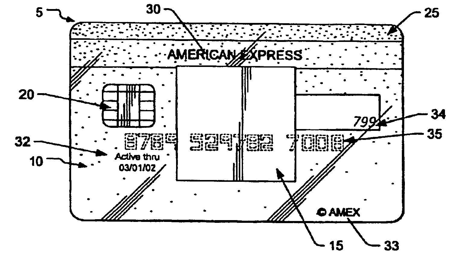
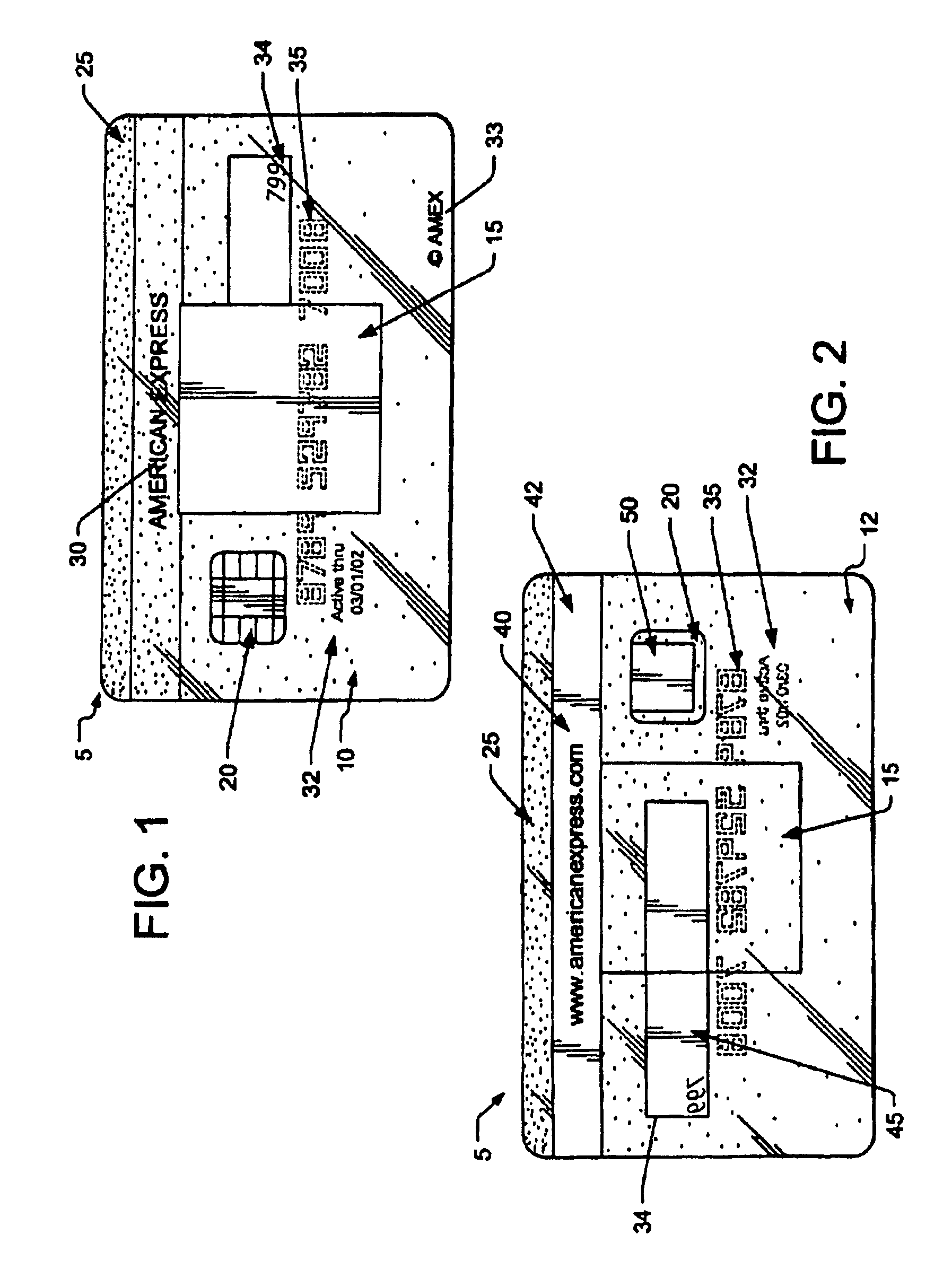
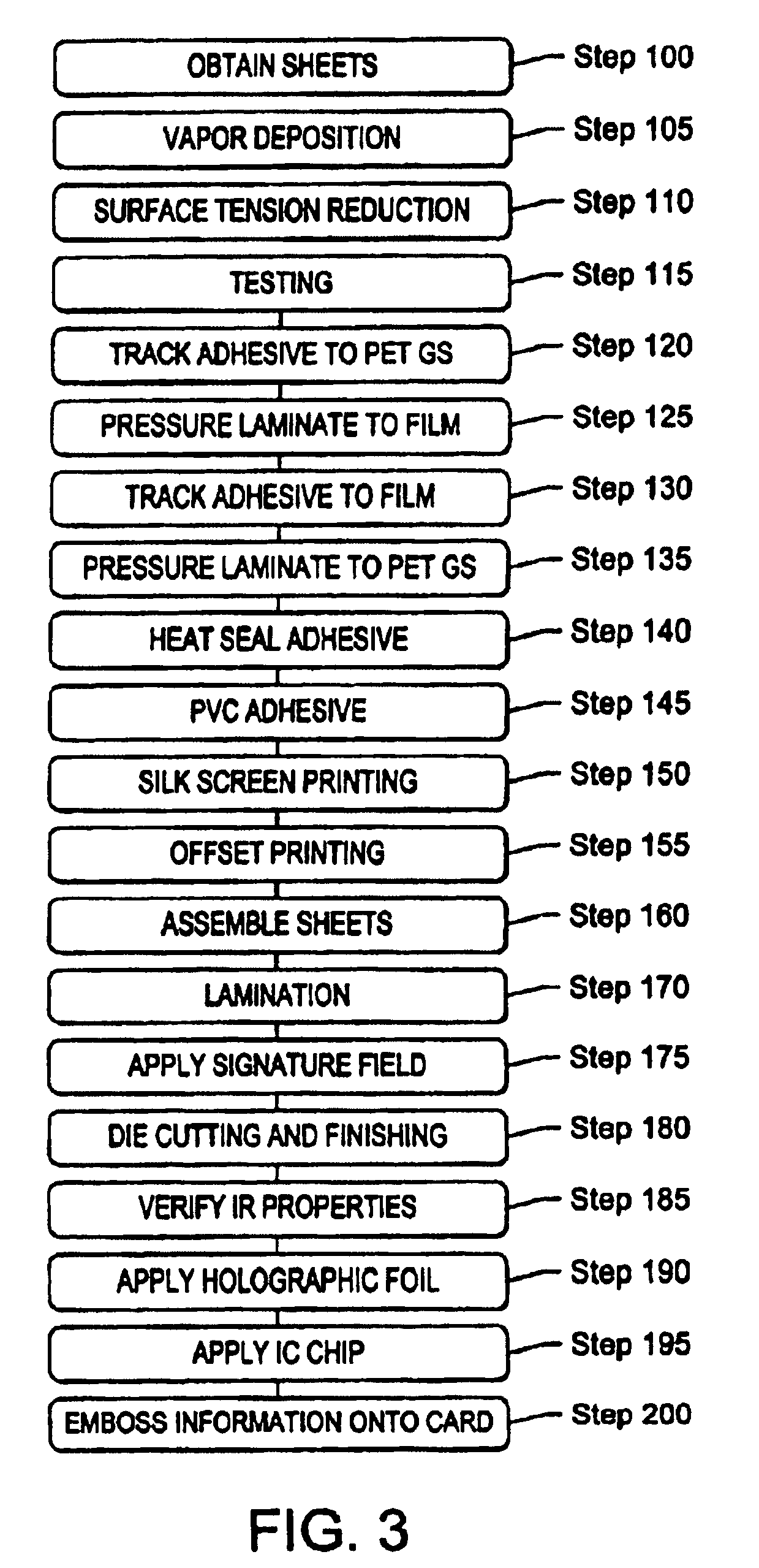
The present invention relates to a process for producing an opaque, transparent or translucent transaction card having multiple features, such as a holographic foil, integrated circuit chip, silver magnetic stripe with text on the magnetic stripe, opacity gradient, an invisible optically recognizable compound, a translucent signature field such that the signature on back of the card is visible from the front of the card and an active thru date on the front of the card. The invisible optically recognizable compound is preferably an infrared ink comprising an infrared phthalocyanine dye, an infrared phosphor, and a quantum dot energy transfer compound. The infrared ink can be detected by a sensor found in an ATM or card assembly line.

Description

CROSS REFERENCE TO RELATED APPLICATIONS[0001]The present application is a Continuation-in-Part Application of U.S. patent application Ser. No. 10 / 394,914, filed Mar. 21, 2003, now U.S. Pat. No. 7,377,443 which is a Continuation Application of U.S. patent application Ser. No. 10 / 092,681, filed Mar. 7, 2002 now U.S. Pat. No. 6,764,014, which is a continuation-in-part application of U.S. patent application Ser. No. 10 / 062,106, filed Jan. 31, 2001 now U.S. Pat. No. 6,749,123, which is a continuation-in-part application of U.S. patent application Ser. No. 09 / 653,837, filed Sep. 1, 2000 now U.S. Pat. No. 6,581,839 and further claims the benefit of U.S. Provisional Application No. 60 / 153,112, filed Sep. 7, 1999; U.S. Provisional Application No. 60 / 160,519, filed Oct. 20, 1999; U.S. Provisional Application No. 60 / 167,405, filed Nov. 24, 1999; U.S. Provisional Patent Application No. 60 / 171,689, filed Dec. 21, 1999 and U.S. patent application Ser. No. 09 / 652,899, entitled “Methods And Apparat...

Claims


Application Information

Patent Timeline
Patent Type & Authority Patents(United States)
IPC IPC(8): G06K19/00
CPCB41M3/14C09D11/037C09D11/50B42D25/00B42D25/378C09D11/32B42D2033/20B32B38/145B32B2425/00B42D2033/04B42D2035/34B42D25/45B42D25/382B42D25/351B32B37/02B32B2307/412B32B2307/422B32B2327/06G06K19/02G06K19/022
Inventor MORRILL WEBB, LISA ANNFAENZA, JR., WILLIAM J.
Owner LIBERTY PEAK VENTURES LLC
Learn More