
Tilt steering column assembly for a vehicle

a technology for tilting steering columns and components, which is applied in the direction of manufacturing tools, transportation and packaging, and the connection of rods, etc., can solve the problems of adversely affecting the cost of manufacturing components, and achieve the effects of reducing tolerance requirements, reducing manufacturing costs, and reducing quality

Inactive Publication Date: 2010-11-23
STEERING SOLUTIONS IP HLDG +1
View PDF16 Cites 0 Cited by
  • Summary
  • Abstract
  • Description
  • Claims
  • Application Information

AI Technical Summary

Benefits of technology

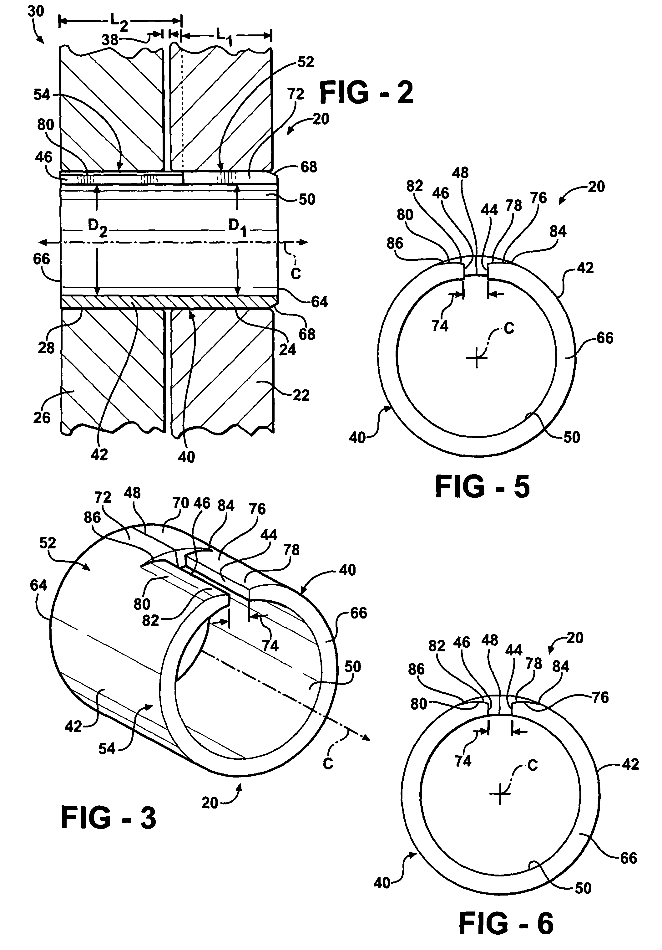
[0005]The present invention provides for a tilt steering column assembly having a first housing defining at least one orifice disposed along a central axis and a second housing defining at least one hole disposed along the central axis. A pin including a body having a first end and a second end facing the first end to define a seam substantially parallel to the central axis is disposed in the orifice and the hole. The assembly includes a pin apparatus having the body. The body defines a bore along the central axis with the body having a first portion disposed in at least one of the orifice and the hole and a second portion extending from the first portion and disposed in another one of the orifice and the hole for coupling the first housing to the second housing. A first tab extends outwardly from a segment of the first end and a second tab extends outwardly from a segment of the second end. The first tab abuts the second tab to define a portion of the seam with a remainder of the first and second ends being spaced from each other to define a gap and a remaining portion of the seam for providing a proper fit of the pin within the orifice and the hole by compensating for varying dimensions of at least one of the orifice and the hole.
[0007]Accordingly, the present invention provides for a pin apparatus able to perform more uniformly over a wider range of tolerances and provide a lash free quality. This pin apparatus reduces the tolerance requirements previously required in tilt steering column assemblies, thereby reducing the manufacturing costs.

Problems solved by technology

In order to achieve a lash free quality of the second portion slip fit into the hole, very close tolerances between the hole and the pin must be maintained which adversely affects the cost to manufacture the components.

Method used


Image

  • Tilt steering column assembly for a vehicle
  • Tilt steering column assembly for a vehicle
  • Tilt steering column assembly for a vehicle

Examples


Embodiment Construction

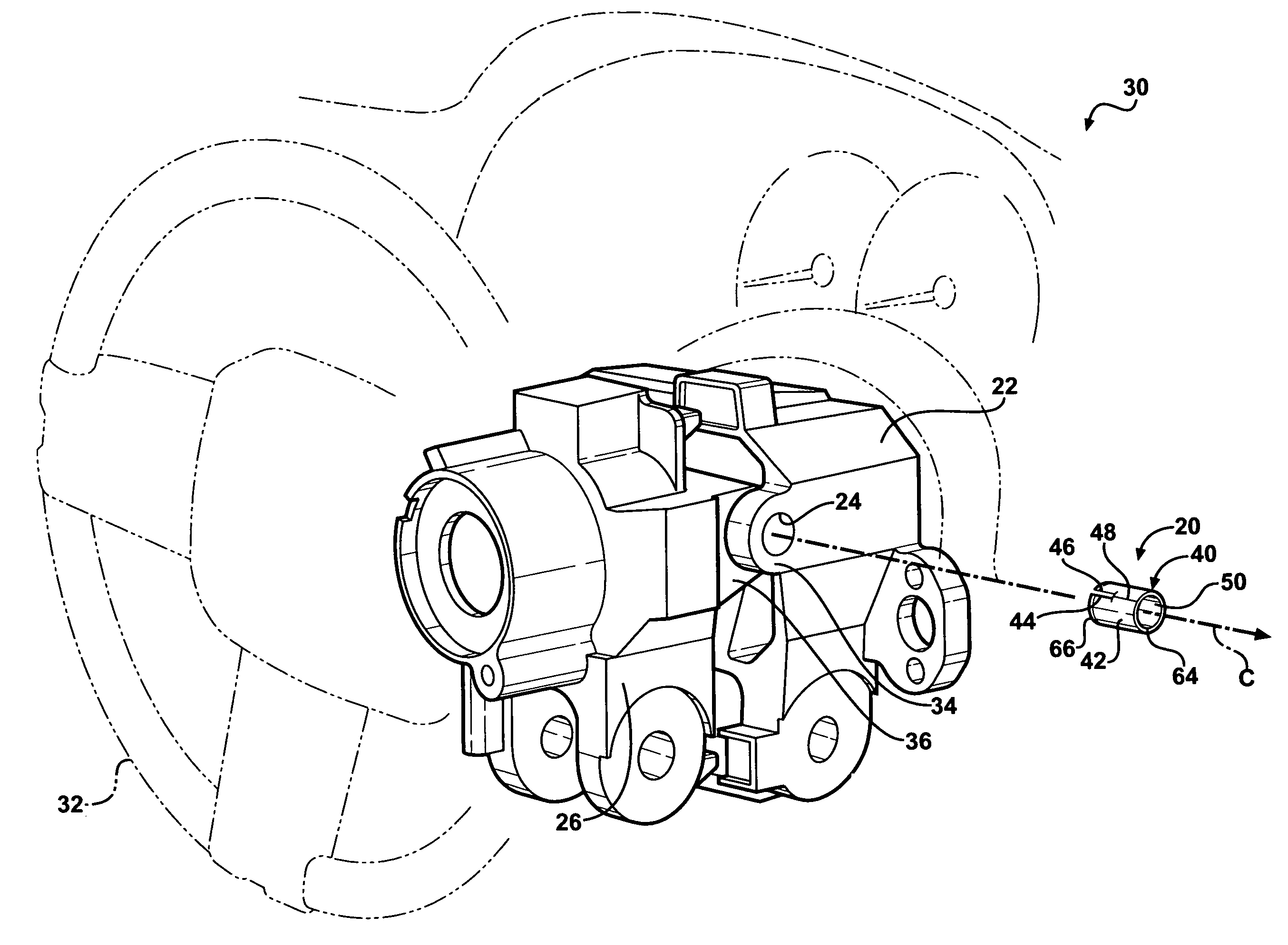
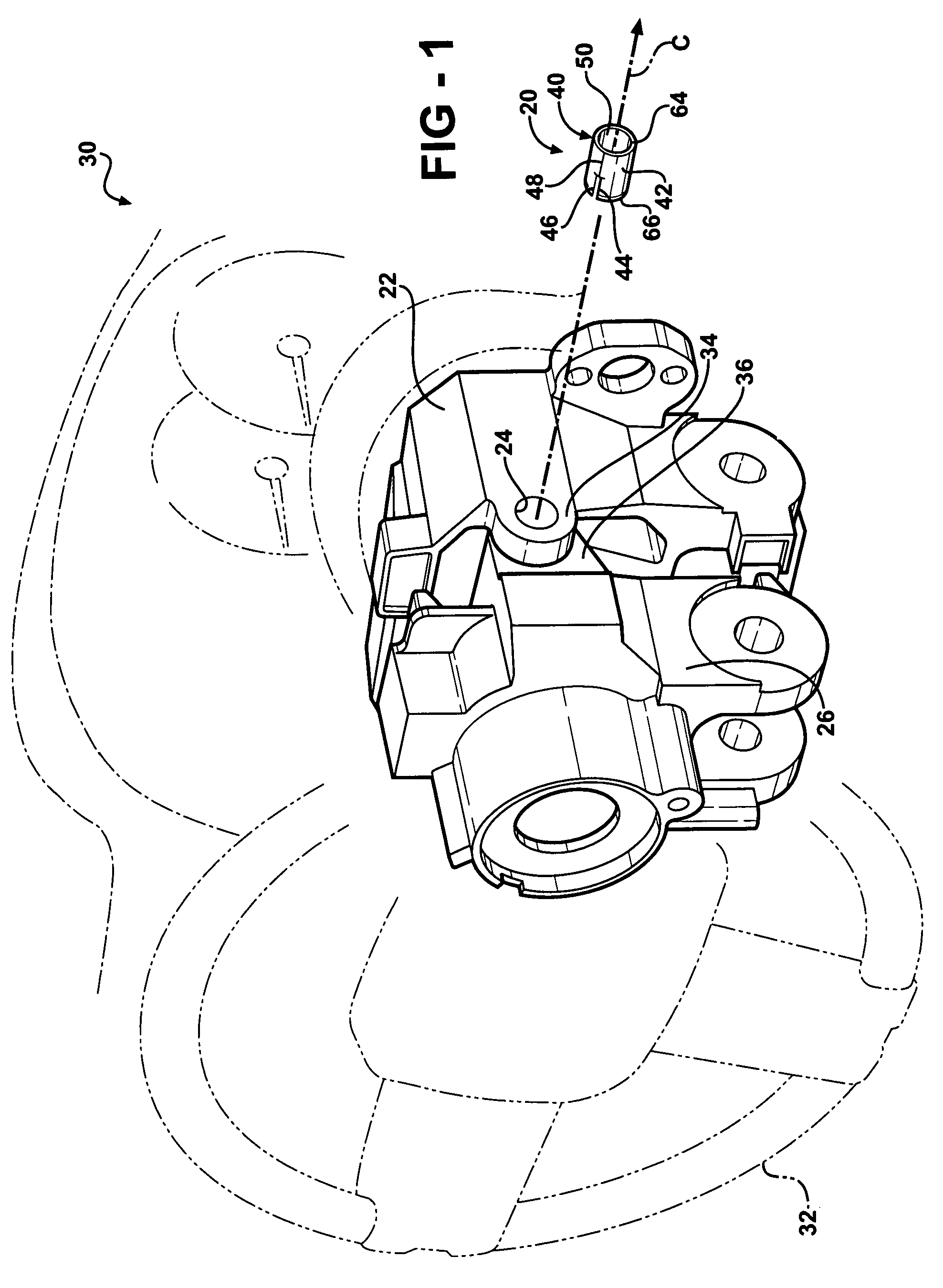
[0021]Referring to the Figures, wherein like numerals indicate like or corresponding parts throughout the several views, a pin apparatus 20 for coupling together a first member 22 defining a orifice 24 along a central axis C and a second member 26 defining an hole 28 along the central axis C is generally shown in FIG. 1.

[0022]In the embodiments shown in FIGS. 1-12, the pin apparatus 20 is adapted to be used in a tilt steering column assembly 30 for a vehicle (not shown). However, it is to be appreciated that the pin apparatus 20 may be used in assemblies other than tilt steering columns. The pin apparatus 20 may be used in any assembly for coupling the first member 22 to the second member 26 and / or with at least one of the first member 22 and the second member 26 rotatable relative to each other. As an example described with reference to FIGS. 1-12, the first member 22 will be referred to as a first housing and the second member 26 will be referred to as a second housing.

[0023]Refer...


PUM

PropertyMeasurementUnit
dimensionsaaaaaaaaaa
lengthaaaaaaaaaa
sizeaaaaaaaaaa

Abstract

A tilt steering column assembly having a first housing defining at least one orifice disposed along a central axis and a second housing defining at least one hole disposed along the central axis is disclosed. A pin includes a body having a first end and a second end facing the first end to define a seam. A first tab extends outwardly from a segment of the first end and a second tab extends outwardly from a segment of the second end. The first tab abuts the second tab to define a portion of the seam with a remainder of the first and second ends being spaced from each other to define a gap and a remaining portion of the seam for providing a proper fit of the pin within the orifice and the hole by compensating for varying dimensions of at least one of the orifice and the hole.

Description

BACKGROUND OF THE INVENTION[0001]1. Field of the Invention[0002]The present invention relates to a tilt steering column assembly for a vehicle. More specifically to a pin apparatus for coupling together a first member and a second member and a method of making a pin formed from a sheet material.[0003]2. Description of the Prior Art[0004]Tilt steering column assemblies are utilized in vehicles for changing a position of a steering wheel upwardly or downwardly relative to a driver of the vehicle. The assembly includes a tilt housing coupled to a support housing by a pin with the tilt housing rotatable relative to the support housing for adjusting the position of the steering wheel. The support housing defines a orifice and the tilt housing defines an hole for receiving the pin. Typically, the pin is formed from steel wire or steel bar that is machined to the proper size. The pin defines a first portion press fit into the orifice of the support housing and a second portion slip fit int...

Claims


Application Information

Patent Timeline
Patent Type & Authority Patents(United States)
IPC IPC(8): B62D1/18
CPCB62D1/187Y10T403/7058Y10T29/49
Inventor BODTKER, JOEN C.
Owner STEERING SOLUTIONS IP HLDG
Learn More