Drawer lock set

a technology for applied in the field of drawing and locking devices, can solve the problems of easy confusion of parts with slight differences, increase manufacturing costs, etc., and achieve the effect of convenient transfer

Inactive Publication Date: 2010-11-23
FEDERAL LOCK
View PDF18 Cites 15 Cited by
  • Summary
  • Abstract
  • Description
  • Claims
  • Application Information

AI Technical Summary

Benefits of technology

[0008]By engaging the first or second notch of the cylinder with the block in the tubular member, the keyhole can be maintain upright and the dead bolt can be changed its operational direction.
[0009]The primary object of the present invention is to provide a drawer lock set wherein the direction that the dead bolt is operated can be easily transferred from one to another with only one part replaced.

Problems solved by technology

The manufacturers have to manufacture the two different bodies 10, 10′ by two different molding units which is costly.
Besides, the parts that have slightly differences are easily confused when assembling the lock sets.
Therefore, the manufacturers have to prepare two molding units for manufacturing the core 30 and the cylinder 20, this increases the manufacturing cost.

Method used


Image

  • Drawer lock set
  • Drawer lock set
  • Drawer lock set

Examples


Embodiment Construction

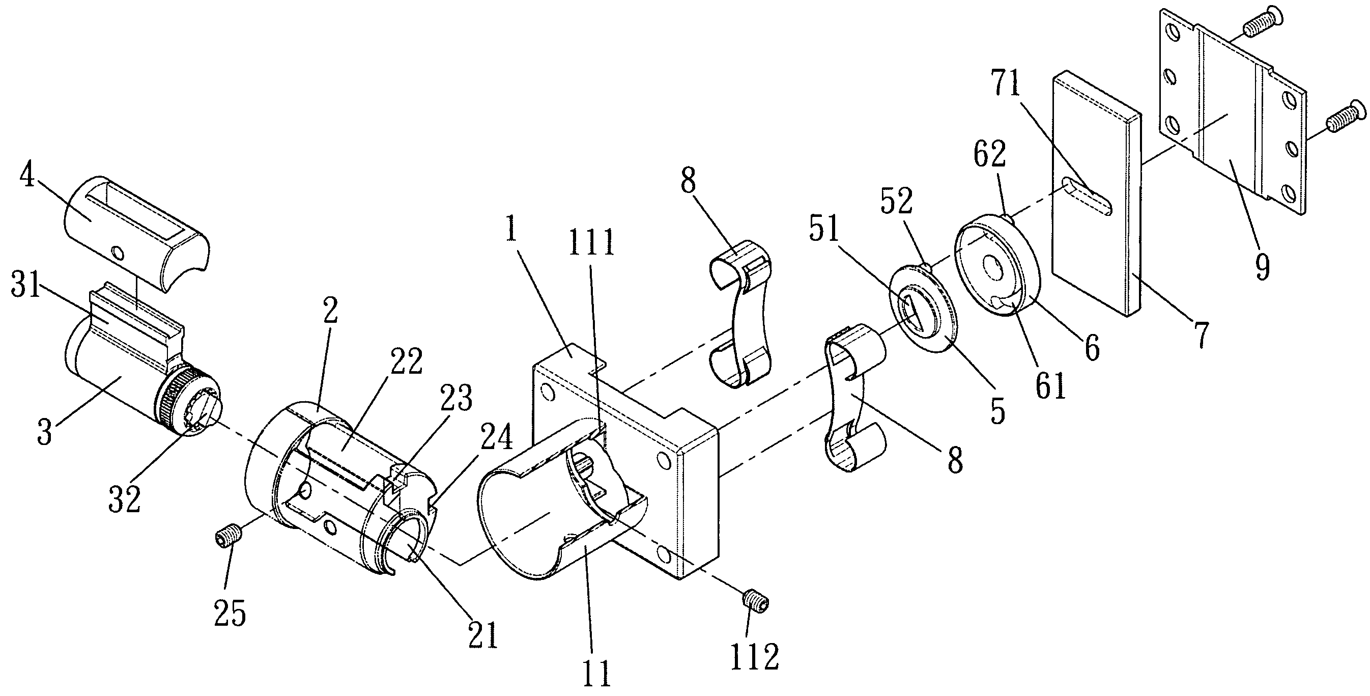
[0022]Referring to FIGS. 6 to 8, the drawer lock set of the present invention comprises a body 1 having a tubular member 11 extending from a first side thereof and a block 111 extends radially from an inner periphery of the tubular member 11. A cylinder 2 is received in the tubular member 11 and fixedly position within the cylinder 2 by a bolt 112 which extends through the tubular member 11 and contacts against the cylinder 2. A first notch 23 and a second notch 24 are defined in an outer periphery of the cylinder 2, a 90-degree angular distance is defined between the first and second notches 23, 24. The block 111 is engaged with one of the first and second notches 23, 24. The cylinder 2 includes a passage 21 defined therein and a reception space 22 is defined in the cylinder 2. The first and second notches 23, 24 are located corresponding to a range of an end of the reception space 22. A core 3 includes a pin frame 31 extending radially therefrom and a cap 4 is mounted to the pin f...


PUM


Abstract

A drawer lock set includes a body with a tubular member and a block extends radially from an inner periphery of the tubular member. A cylinder and a core are received in the tubular member. The core includes a driving piece extending from a distal end thereof and is capable of driving a transmission member which is able to rotate a driving member. The driving member includes a protrusion which is slidably engaged with a groove defined in the dead bolt. The cylinder includes a first notch and a second notch in an outer periphery thereof and a 90-degree angular distance is defined between the first and second notches. The block is engaged with one of the first and second notches so as to set the position of the operational direction of the dead bolt with only one part replaced.

Description

FIELD OF THE INVENTION[0001]The present invention relates to a lock set, and more particularly, to a drawer lock set whose dead bolt can be operated in four different directions.BACKGROUND OF THE INVENTION[0002]A conventional drawer lock set includes a dead bolt which can be operated by using a key to lock or unlock the drawer. Generally, the dead bolt of the conventional drawer lock set can be operated vertically as shown in FIGS. 1 and 2, and operated horizontally as shown in FIGS. 3 and 4. Both of the two types of the conventional drawer lock sets includes a body 10 / 10′ and a tubular member 101 extends from the body 10 / 10′. An elongate ridge 1011 and an elongate groove 1012 are located in the inner periphery of the tubular member 101. A cylinder 20 receives a core 30 therein and both of which are inserted into the tubular member 101. The cylinder 20 includes a passage 201 through which the pin frame 301 on the core 30 can slide therein. The cylinder 20 further includes an elongat...

Claims


Application Information

Patent Timeline
Patent Type & Authority Patents(United States)
IPC IPC(8): E05B9/04E05B65/46
CPCE05B63/0056E05B65/46Y10S70/42Y10T70/5111Y10T70/7718Y10T70/8541Y10T70/8865Y10T70/7655Y10T70/8838Y10T70/5133Y10T70/7712Y10T70/7678Y10T70/7706
Inventor LIU, TIEN-KAO
Owner FEDERAL LOCK
Why Eureka
Try Eureka