
Method and its apparatus for detecting defects

a technology of inspection apparatus and defect, applied in the direction of measuring devices, instruments, scientific instruments, etc., can solve the problems of failure of hard disk apparatus, crystal defect embedded, and inability to provide cut edges such as notch,

Inactive Publication Date: 2010-11-16
HITACHI HIGH-TECH CORP
View PDF5 Cites 7 Cited by
  • Summary
  • Abstract
  • Description
  • Claims
  • Application Information

AI Technical Summary

Benefits of technology

[0015]According to the present invention, in the case of inspecting a circular sample such as a disk substrate, which cannot prepare position standard, processing of the inspected data based on the same standard exerts effects of enabling mutual comparison or check from a plurality sets of a inspected data, and correct understanding of a state of increase or decrease in defects data, coincidence or non-coincidence of inspected data, and understanding of defects generating state, early stage finding of critical defects, and correct understanding of production apparatus condition.

Problems solved by technology

Recently, with improvement of recording density in a hard disk apparatus, spacing (hereafter referred to as a flying height) between a head for recording and writing (hereafter referred to as a head) and a disk substrate has extremely been narrowed as small as several tens nm to several nm; therefore, presence of depression / protrusion defects larger than the flying height, on this disk substrate, makes the disk substrate and the head contacted, and causes failure of a hard disk apparatus.
These defects include crystal defects embedded inside a disk substrate material, residue of abrasive grains, or fine scratch (scratch or the like) generating in polishing for improvement of flatness of a disk substrate, or foreign matters adhering in cleaning or drying or the like.
However, crystal defects or scratch or the like cannot be corrected, resulting in handling as a defect product; therefore, to ensure high yield and high reliability of a hard disk apparatus, early stage removal of a disk substrate having such defects is important.
In addition, also after vapor deposition of a magnetic substance, the above defects are considered to be generated by certain causes, therefore surface state inspection is also necessary.
Therefore, a cut edge such as a notch cannot be provided, like a wafer used in production of a semiconductor device.
In addition, because a whole surface of a disk substrate is used for magnetic recording, pattern recording for a servo drive or the like, marking at the outer circumference or inner circumference is usually not allowed.
However, once a disk substrate is taken out from the inspection apparatus, the coordinates are reset, and thus, even when the same disk substrate is re-inspected, coincidence of coordinates with the previous inspection results is difficult; that requires comparison using defects map output by each inspection, on difference in kinds, coordinates and number of defects by each of the inspections.
Therefore, in the case of a plurality of inspections, and coordinate origins of defects maps output by each of the inspections do not coincide, a problem is raised that determination on whether or not the defects are the same defect, or foreign matters adhered this time is ambiguous, from information on the defect maps outputs.
In addition, also in carrying out surface inspections before and after a production step, insufficient inspected data makes discrimination difficult whether or not defects are newly generated in the production step, or generated in previous steps from the production step thereof, resulting in correct determination impossible on a state of a production apparatus.
Furthermore, in the case of defects matching in an apparatus other than surface inspection apparatus, which is capable of similarly outputting defects in a rotation direction and in a radius direction (for example, an inspection apparatus of magnetic characteristics, described in JP-A-2000-57501), coordinate coincidence is difficult; therefore, even by analysis back to the previous steps, when critical defects generates, sufficient analysis may be inhibited because coordinates provide no coincidence, or insufficient matching.
As described above, a conventional inspection apparatus gave no consideration of use of inspected data for analysis, which raised a problem of inability of mutual determination by inspected data.
Because there was no consideration of inspected data of detected results for mutual utilization, in an inspection apparatus for inspecting a circular sample such as a disk substrate, which cannot prepare position standard, inspected data could not effectively be utilized.

Method used


Image

  • Method and its apparatus for detecting defects
  • Method and its apparatus for detecting defects
  • Method and its apparatus for detecting defects

Examples


Embodiment Construction

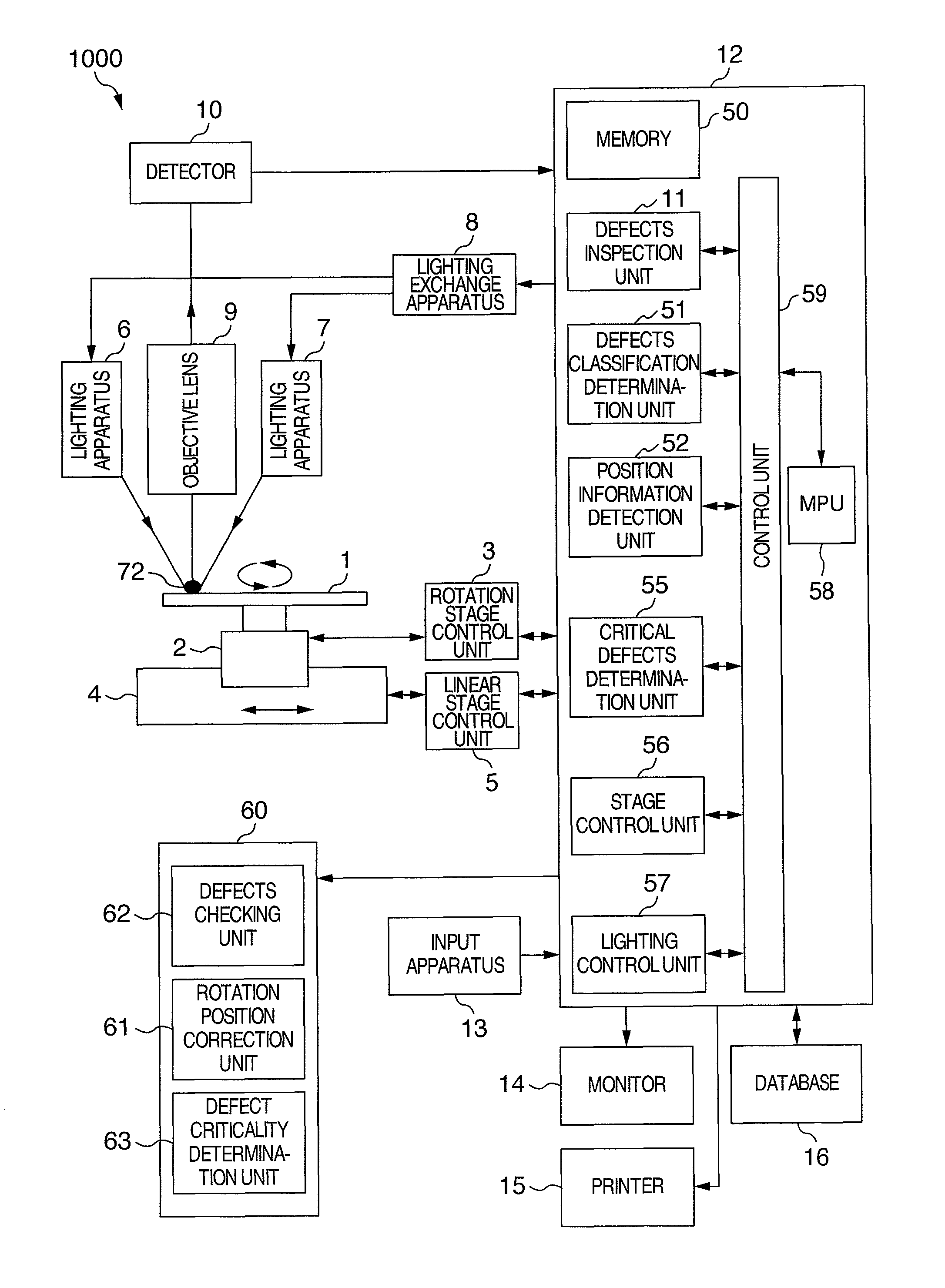
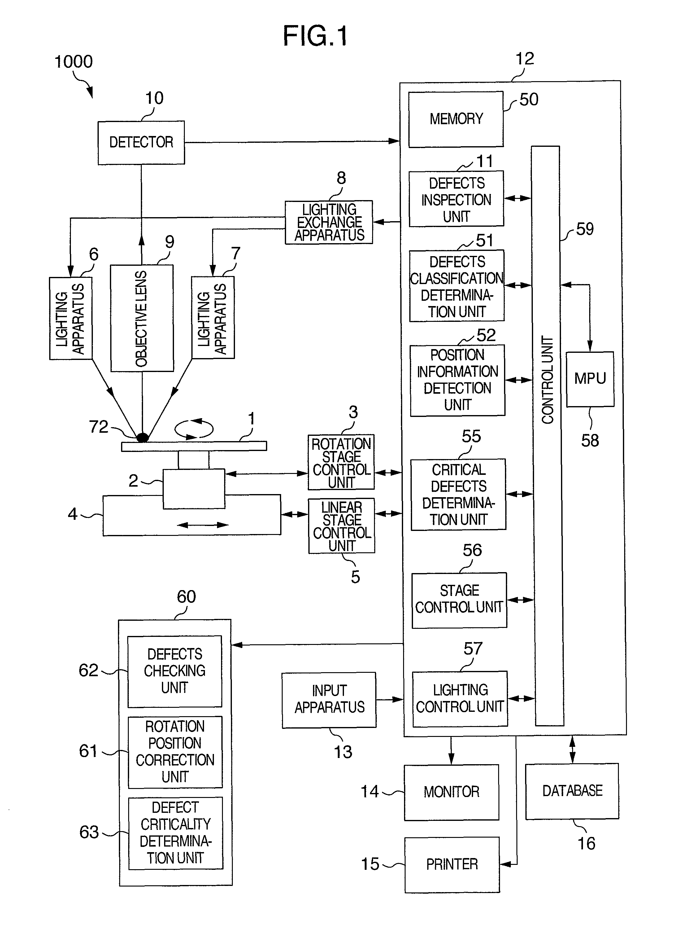
[0027]The present invention relates to a method for defects inspection, which is capable of mutual utilization of inspected data obtained by inspections using a plurality of inspection apparatuses, by correction of coordinates of a plurality sets of an inspected data, in the case of processing each inspected data obtained by inspections using a plurality of inspection apparatuses on the same disk substrate, in inspecting a disk substrate, which cannot set position standard, and is provided with data processing function, so that inspected data is effectively utilized; and an apparatus therefor.

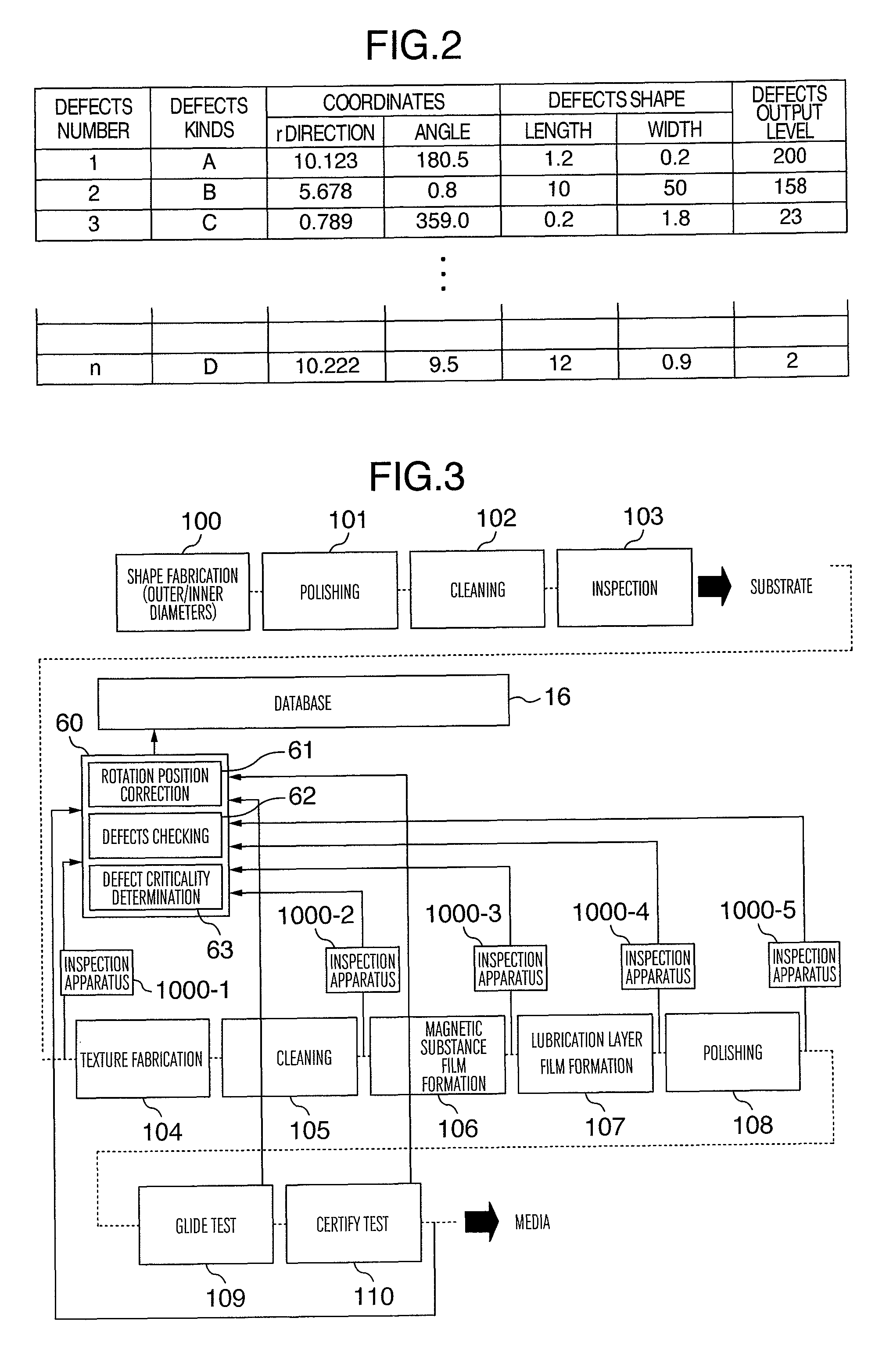
[0028]The present invention can be used, in the case of inspecting on the same inspection step, using a plurality of defects inspection apparatuses, for evaluation of variation (instrumental error) in detection sensitivity among a plurality of defects inspection apparatuses, by checking inspected data among each of the inspection apparatuses, and matching sensitivity among each of the defects i...


PUM

PropertyMeasurementUnit
first defect inspection apparatusaaaaaaaaaa
defect inspectionaaaaaaaaaa
first defect inspectionaaaaaaaaaa

Abstract

In the present invention, to make corrective matching thereof, it is designed as follows; position effect of defects coordinates, which are output from an inspection apparatus, is allowed, coordinates of inspected data are mutually corrected, and a state of coincidence or non-coincidence among a plurality sets of inspected data is output or displayed. Inspection data is designed to include kinds, kinds difference and dimension of defects. A state of coincidence or non-coincidence between inspected data is designed to be output or displayed appropriately, by kinds or dimensions, or by a grouping thereof, of a defects object. The same sample is inspected by every time of passing a production step, and a state of data increase or decrease, or coincidence or non-coincidence between the inspected data is designed to be output or displayed.

Description

INCORPORATION BY REFERENCE[0001]The present application claims priority from Japanese application JP2006-103732 filed on Apr. 5, 2006, the content of which is hereby incorporated by reference into this application.BACKGROUND OF THE INVENTION[0002]The present invention relates to a defects inspection apparatus of a magnetic disk substrate or a semiconductor wafer or the like, in particular, relates to, in a method for mutually comparing or checking a plurality sets of a detected data obtained by repeated inspection of the same substrate, or a plurality sets of an inspected data obtained by inspection of the same substrate using an inspection apparatus before and after process treatment, a defect inspection method, wherein a state of defects coincidence or non-coincidence is output or displayed; and an apparatus therefor.[0003]As a magnetic recording medium used in a hard disk apparatus, a disk substrate vapor deposited with a magnetic substance is used. Data is magnetically recorded ...

Claims


Application Information

Patent Timeline
Patent Type & Authority Patents(United States)
IPC IPC(8): G01N21/00
CPCG01N21/4738G01N21/9501
Inventor YOSHIDAMAEDA, SHUNJI
Owner HITACHI HIGH-TECH CORP
Learn More