
Fire detector using a laser range finder, an infrared camera and a charged coupled device camera

a laser range finder and fire detector technology, applied in the field of system and method for detecting fires, can solve the problems of large damage that is too large for human beings to even estimate the extent, large difficulty in using the above methods, and difficulty in detecting the accurate location and angle at which a fire has broken ou

Inactive Publication Date: 2010-11-16
CHANG SUNG CO LTD
View PDF7 Cites 4 Cited by
  • Summary
  • Abstract
  • Description
  • Claims
  • Application Information

AI Technical Summary

Benefits of technology

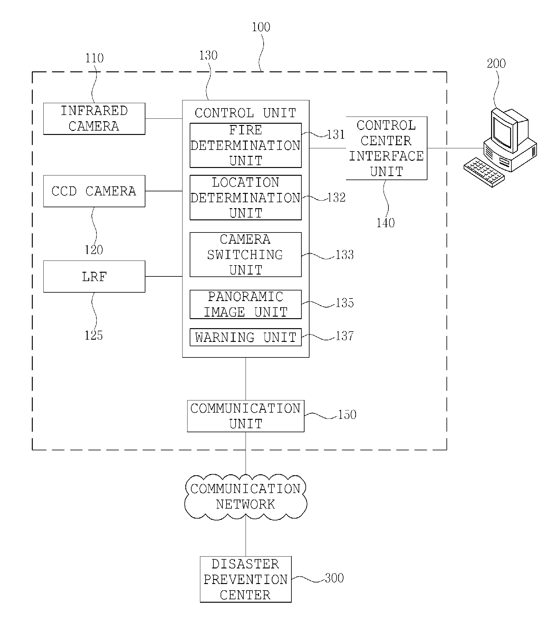
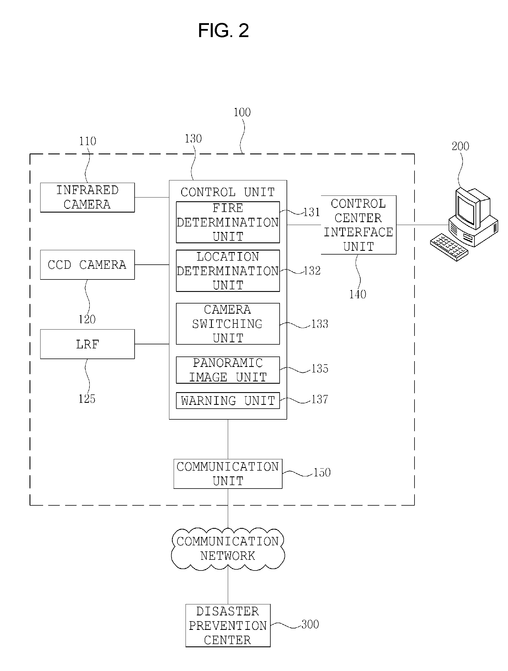
"The present invention provides a system and method for detecting fire using infrared cameras and a laser range finder. The system can capture images of an area on fire and determine its size and speed of spreading. The system can also automatically determine if a fire has broken out and capture the image of the area on fire. The system can output the image to a control center terminal and control a warning unit, such as a sound or message, to alert firefighters. The invention aims to provide a more effective and efficient system for detecting fire and preventing damage."

Problems solved by technology

Generally, fires are disasters causing damage that is too large for human beings to even estimate the extent thereof because they not only injure human lives and burn buildings and articles, but also, in the case of forest fires, destroy trees and forests which have grown over a period ranging from several tens of years to several hundreds of years or several thousands of years.
The methods using thermal sensors or smoke sensors may be effectively used in a limited area such as in an indoor environment, but there is large difficulty in using the above methods when the area to be monitored is an outdoor environment as is the case concerning forest fires.
Furthermore, in the case of fire monitoring using images, it is difficult to detect an accurate location and angle at which a fire has broken out.

Method used


Image

  • Fire detector using a laser range finder, an infrared camera and a charged coupled device camera
  • Fire detector using a laser range finder, an infrared camera and a charged coupled device camera
  • Fire detector using a laser range finder, an infrared camera and a charged coupled device camera

Examples


first embodiment

[0061]Referring to FIG. 4, in a first embodiment, the fire determination unit 131 accesses the captured image received from the infrared camera 110 at step S111. Thereafter, the fire determination unit 131 determines whether an area having a temperature equal to or greater than a reference temperature (for example, 200° C.) is present in the captured image at step S112.

[0062]If it is determined at step S112 that the area having a temperature equal to or greater than the reference temperature is present, the fire determination unit 131 determines the area to be an area on fire, and generates the contour of the area on fire by extracting the contour of the image of the area on fire at step S113. Further, the fire determination unit 131 generates a basic contour by extracting the contour of the image of the area before the fire breaks out, compares the contour of the area on fire with the basic contour at step S114, and determines a matching area to be an ignition area and the remainin...

second embodiment

[0063]Referring to FIG. 5, in a second embodiment, the fire determination unit 131 accesses the captured image received from the infrared camera 110 at step S116. Thereafter, the fire determination unit 131 determines whether an area having a temperature equal to or greater than a reference temperature (for example, 200° C.) is present in the captured image at step S117.

[0064]If it is determined at step S117 that the area having a temperature equal to or greater than the reference temperature is present, the fire determination unit 131 determines the area to be an area on fire, and generates the contour of the area on fire by extracting the contour of the image of the area on fire at step S118. When the contour continuously varies for a preset period of time or longer (for example, a swaying pattern of a reddish color) at step S119, the fire determination unit 131 determines the contour area to be a flame at step S120.

[0065]In this case, if it is determined by the fire determination...


PUM


Abstract

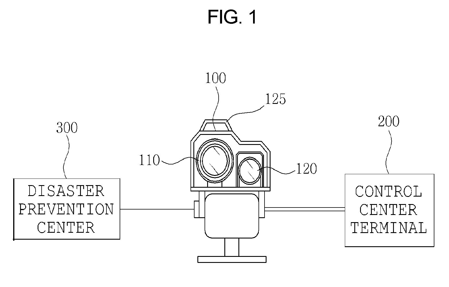
A system and method for detecting a fire includes a fire detection device and a control center terminal. The fire detection device includes an LRF for calculating a distance to a location of breakout of a fire using a laser. An infrared camera captures an infrared image and transmits the infrared image to a control unit. A CCD camera captures a CCD image and transmits the CCD image to the control unit. The control unit analyzes the infrared image, determines whether a fire has broken out, performs processing such that the CCD camera captures an area on fire, determines the location of breakout of the fire, performs processing such that the captured image is output to the control center terminal, and controls a function of a warning unit. The warning unit outputs a warning sound or a warning message.

Description

CROSS REFERENCE[0001]This application claims foreign priority under Paris Convention and 35 U.S.C. §119 to Korean Patent Application No. 10-2008-0111793, filed Nov. 11, 2008 with the Korean Intellectual Property Office.BACKGROUND OF THE INVENTION[0002]1. Field of the Invention[0003]The present invention relates, in general, to a system and method for detecting a fire, and, more particularly, to a method and system for detecting a fire, in which a fire detection device equipped with a Laser Ranger Finder (LRF) captures an image required to detect a fire and analyzes the shape pattern of the image, and allows accurate and prompt determination as to whether a fire has broken out or not and where, thus providing a suitable warning.[0004]2. Description of the Related Art[0005]The present invention relates to a system and method for detecting a fire.[0006]Generally, fires are disasters causing damage that is too large for human beings to even estimate the extent thereof because they not o...

Claims


Application Information

Patent Timeline
Patent Type & Authority Patents(United States)
IPC IPC(8): G08B17/12
CPCG08B17/125H04N5/23238H04N5/33H04N23/698H04N23/20G08B13/196G08B25/00G08B13/19H04N7/18
Inventor LEE, YEU YONG
Owner CHANG SUNG CO LTD
Learn More