
Method and apparatus for implanting an aortic valve prosthesis

a technology for aortic valves and prostheses, applied in balloon catheters, medical science, surgery, etc., can solve the problems of high risk, present problems for patients who cannot be operated, and patients who could be operated, and achieve the effect of low risk of morbidity and mortality, and minimal blood loss

Inactive Publication Date: 2010-11-16
REYNOLDS M DELGADO III
View PDF21 Cites 0 Cited by
  • Summary
  • Abstract
  • Description
  • Claims
  • Application Information

AI Technical Summary

Benefits of technology

[0014]The method and apparatus for implanting an aortic valve of the present invention, when compared to previously proposed methods and apparatus, is believed to have the advantages of: not requiring surgery, or incisions, upon the heart itself, may be readily performed percutaneously without chest surgery and without complete loss of blood flow from the heart to the patient's body; and may be transluminally implanted in a cardiac catheterization lab setting with minimal blood loss and relatively low risk of morbidity and mortality.

Problems solved by technology

Such conventional surgical techniques to repair or replace valves, such as aortic valves, present problems for patients who cannot be operated on because of an associated disease or very old age, or present problems for patients who could be operated on, but only at a very high risk.
A major disadvantage associated with the use of such a technique is that when the new aortic valve prosthesis is being deployed within the diseased aortic valve, the patient will have a period of loss of all blood flow during the period of time that the aortic valve prosthesis is being implanted.
Because of this serious disadvantage, the time taken to implant such an aortic valve prosthesis must be kept to a minimum, which in turn may affect the success of the implantation of the aortic valve prosthesis securely within the diseased aortic valve, or may affect the positioning of the aortic valve prosthesis in an optimal position within the diseased aortic valve.

Method used


Image

  • Method and apparatus for implanting an aortic valve prosthesis
  • Method and apparatus for implanting an aortic valve prosthesis
  • Method and apparatus for implanting an aortic valve prosthesis

Examples


Embodiment Construction

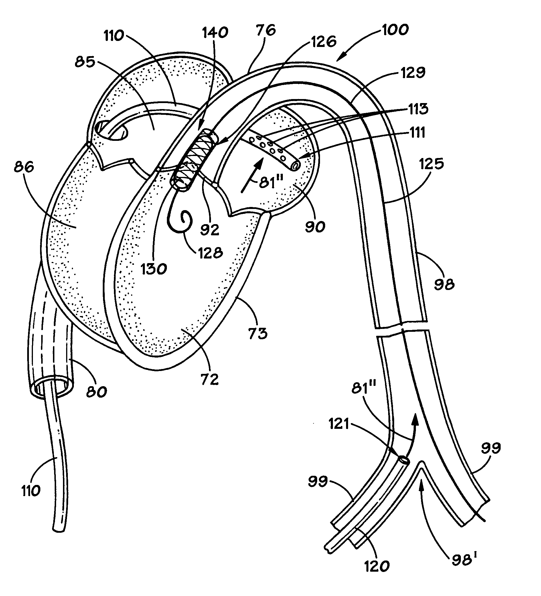
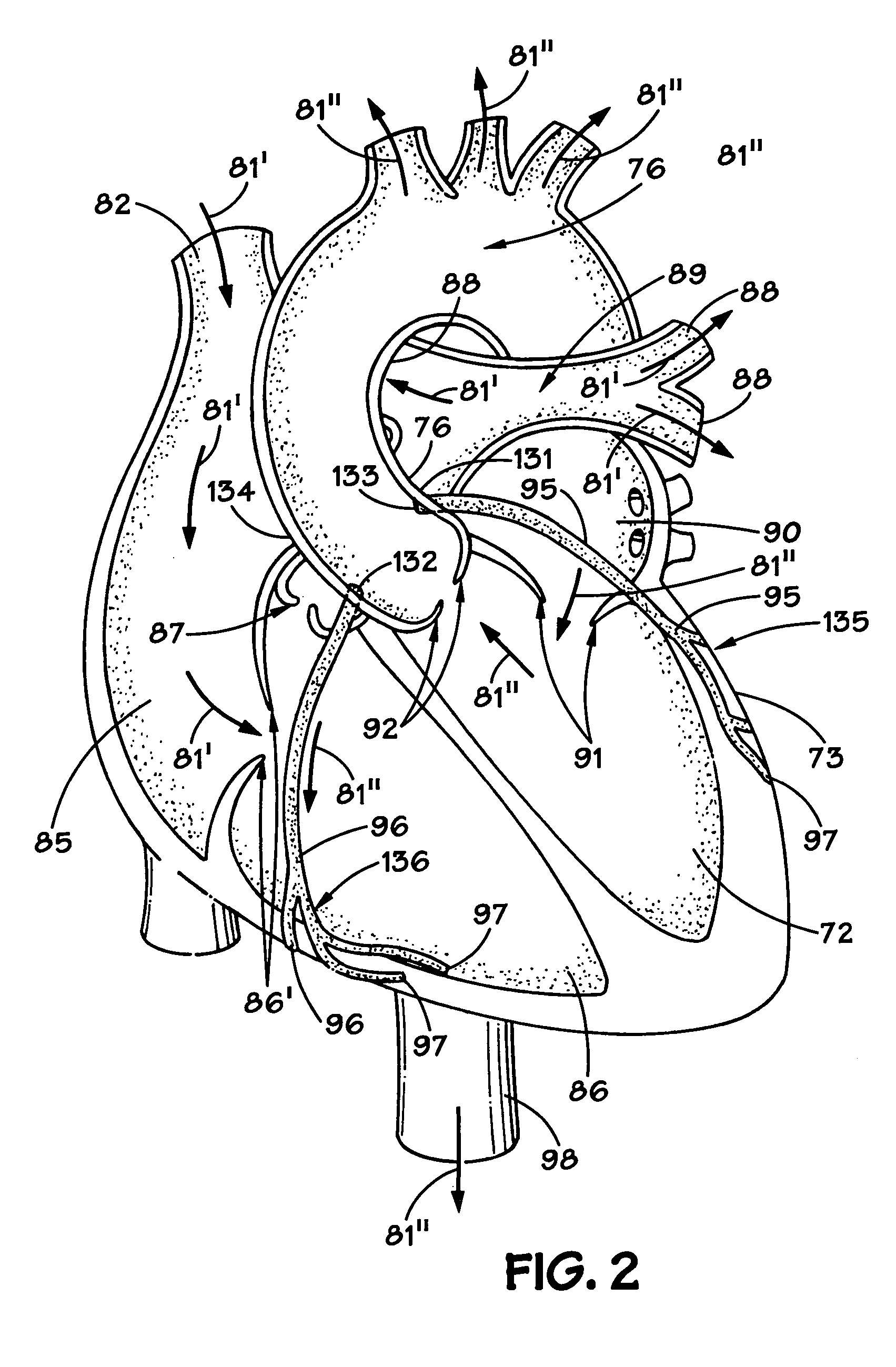
[0022]Before describing the method and apparatus of the present invention, a brief description of the functioning of heart 73 (FIG. 2) and associated arteries is provided. In general, the heart 73 consists of two pumps lying side by side. Each pump has an upper chamber, or atrium, and a lower chamber, or ventricle, as will hereinafter be described. Heart 73 functions to provide a person's body 79 (FIG. 1) with a continuous supply of blood as illustrated by arrows 81. In general, the right side of heart 73 receives “used” blood from the veins (not shown) of a person's body, and this blood is pumped to the lungs (not shown) of the person's body to be oxygenated. The oxygen-rich blood from the lungs is then returned to the left side of the heart, which pumps it through the various arteries. Heart 73 requires its own supply of blood to keep it beating. Oxygen-rich blood is pumped to the chambers, or ventricles, of the heart through the coronary arteries, as will be hereinafter described...


PUM


Abstract

A method and apparatus for percutaneously implanting an aortic valve prosthesis includes a pump for pumping oxygenated blood from the left atrium into the descending aorta, during a period of time in which an aortic valve prosthesis is being implanted within a diseased aortic valve. First and second catheters are associated with the pump, and a third catheter has an end which is adapted for insertion into the ascending aorta, and the third catheter has an aortic valve prosthesis associated with another end of the third catheter.

Description

RELATED APPLICATION[0001]This application claims the benefit and the priority of U.S. Provisional patent application Ser. No. 60 / 675,977 filed Apr. 29, 2005, and entitled “Method and Apparatus for Implanting an Aortic Valve Prosthesis.”BACKGROUND OF THE INVENTION[0002]1. Field of the Invention[0003]The invention relates to a method and apparatus for percutaneously implanting an aortic valve prosthesis.[0004]2. Description of the Related Art[0005]Typically, in the case of valvular heart diseases, valvular defects are repaired by a surgical valve implantation which requires thoracotomy and extracorporeal circulation, which may include placing the patient on a heart-lung machine. Such conventional surgical techniques to repair or replace valves, such as aortic valves, present problems for patients who cannot be operated on because of an associated disease or very old age, or present problems for patients who could be operated on, but only at a very high risk. For example, in the case o...

Claims


Application Information

Patent Timeline
Patent Type & Authority Patents(United States)
IPC IPC(8): A61F2/24
CPCA61F2/2427A61M1/3659A61F2/2433
Inventor DELGADO, III, REYNOLDS M.KAR, BISWAJIT
Owner REYNOLDS M DELGADO III
Learn More