
Variable time division multiplex transmission system

a transmission system and variable time division technology, applied in multiplex communication, data switching networks, instruments, etc., can solve the problems of redundant information, destination address, and insufficient transmission information, and achieve efficient or optimal communication without a single transmission path

Inactive Publication Date: 2010-11-09
TEXAS INSTR INC
View PDF36 Cites 18 Cited by
  • Summary
  • Abstract
  • Description
  • Claims
  • Application Information

AI Technical Summary

Benefits of technology

This patent describes a method for transmitting data on multiple channels using a single transmission path with time division multiplexing. The method allows for the allocation of transmission paths to different channels at different rates, and the use of consecutive time slots for each channel. The allocation of time slots can be variable or predetermined, and the system can include a daisy chain connection line for transferring the allocation of time slots between channels. The method also allows for the identification of channel devices using channel device group identifiers and the allocation of time slots based on the number of time slots used. The technical effects of this patent include improved data transmission efficiency and flexibility in channel allocation.

Problems solved by technology

Therefore, in systems in which multiple channels with different amounts of information or transmission speeds are mixed, the problem arises where efficient or optimal communication will not be accomplished using a single transmission path.
Also, time slots are allocated as necessary in asynchronous multiplex systems, so that while the time slots are used efficiently, there is the problem that redundant information, such as the destination address, is included in the transmitted information.
They are also problems such as the following in the methods where the transmission path is allocated to different channels in time division multiplex communication.
Because of this, system connections will have to be changed, and programs, etc. will have to be changed, and the problem is that the overall system lacks flexibility.
The problems are that this system also lacks system flexibility, and device selection signals are required for the number of devices.
Because of this, in systems such as audio components, it is not possible to simply replace, the device used with a device from a different manufacturer, even if it is the same time of device.
Another problem is that, in order to use several of the same type of device in a system, devices with the same device identifier cannot be used, so that multiple device identifiers are printed on the ROM for one device as a countermeasure, and it must be possible to select one of them when a device is used.

Method used


Image

  • Variable time division multiplex transmission system
  • Variable time division multiplex transmission system
  • Variable time division multiplex transmission system

Examples


Embodiment Construction

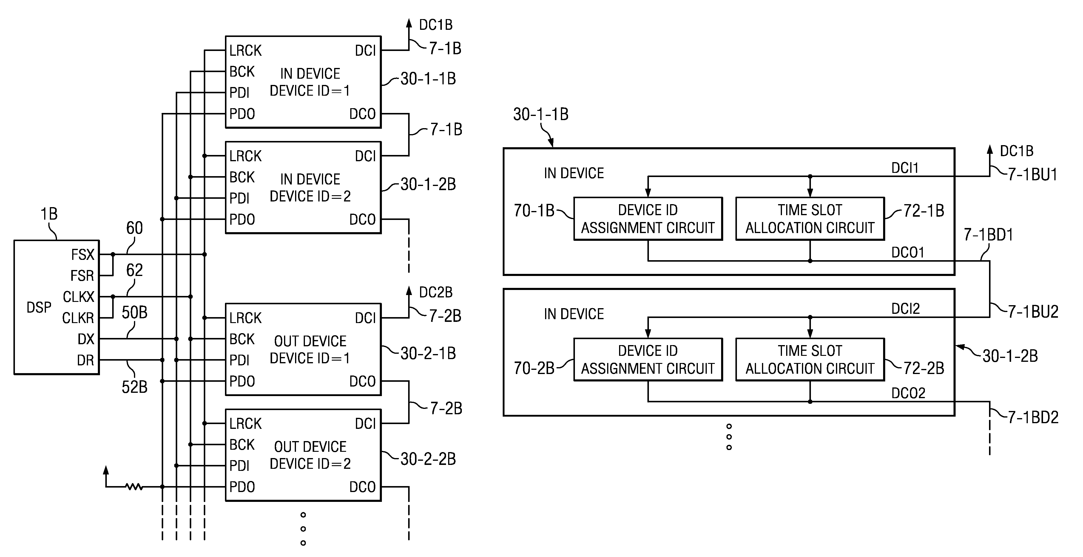
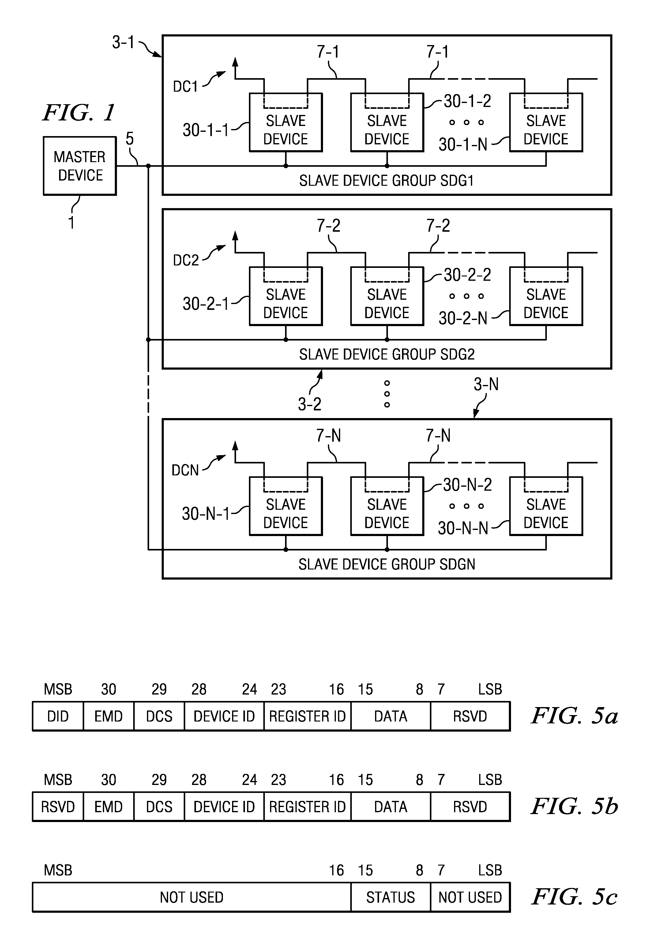
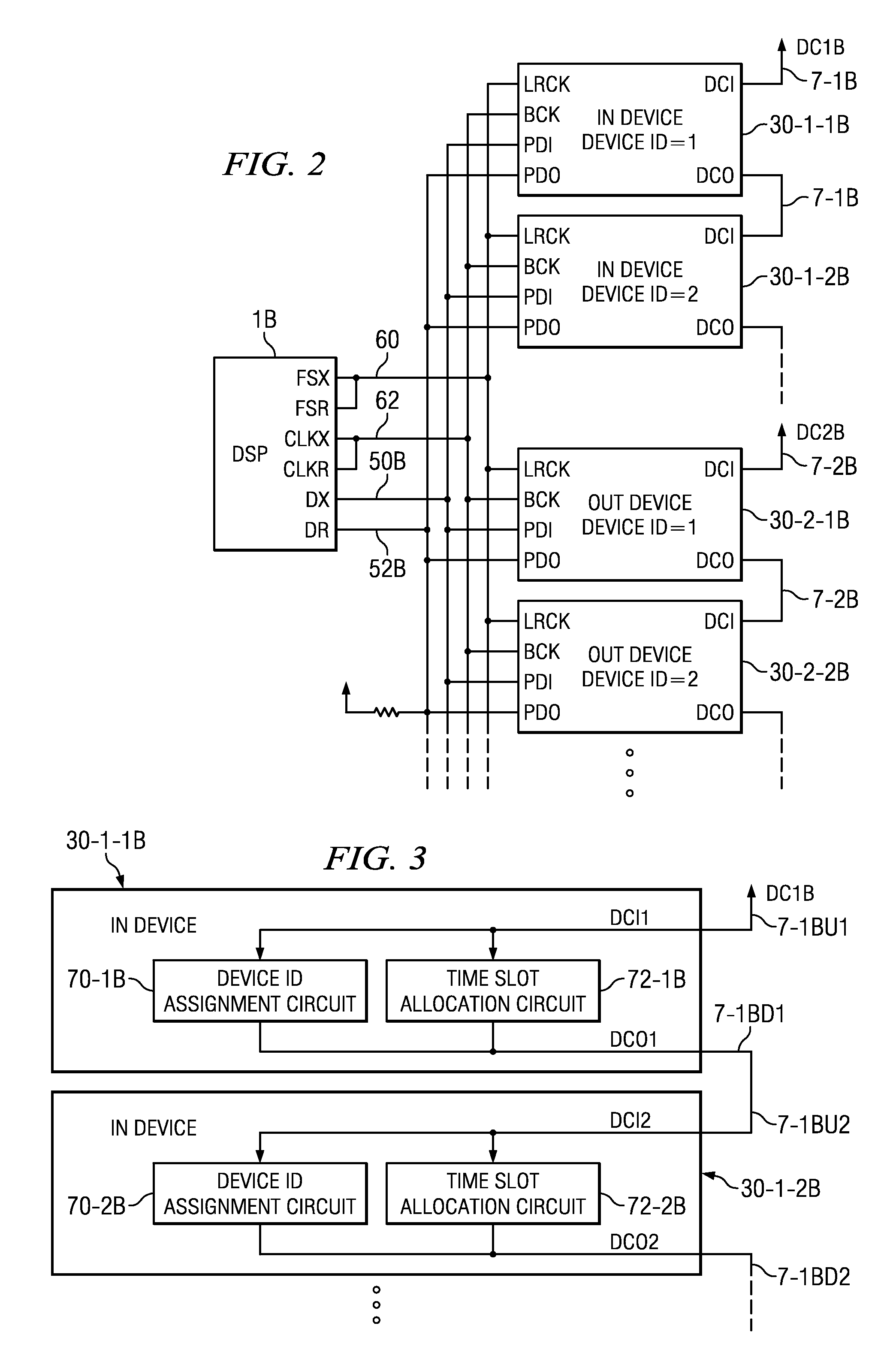
[0040]Next, an embodiment of this invention will be explained in detail with reference to the figures. Note that, in the embodiment below, “channel” is explained as a channel for data to be transmitted between a master device and a slave device in a communication system. And “channel device” is explained as the portion of the channel in the slave device (for example, the IN device or OUT device discussed below) and master device by which the channel is realized.

[0041]First, communication system A, which is an embodiment of a basic constitution that incorporates this invention, is shown in FIG. 1. This system A includes one master device 1, multiple slave device groups 3-1˜3-N (SDG1˜N), and bus 5 that connects each of the slave device groups and master device 1. Each slave device group is furnished with at least one device, for example, multiple slave devices 30-1-1˜30-1-N, or 30-2-1˜30-2-N as shown. Each of these slave devices is connected to bus 5. Communication system A is further...


PUM


Abstract

A time division multiplex transmission system transmits information on multiple channels by using a transmission path with variable time division multiplexing. The variable time division multiplex transmission system of this invention is equipped with multiple channel devices 30 and a single transmission path 5 connected to these multiple channel devices. The multiple channel devices 30 transmit or receive data over the transmission path. Additionally, the system is equipped with a circuit that determines consecutive time slots for using the transmission path, and each of the channel devices transmits or receives data using consecutive time slots. Data can be transmitted in two or more different transmission bands, and the different transmission bands are realized by making the number of time slots used for a communication frame different.

Description

FIELD OF THE INVENTION[0001]This invention relates in general to communication. In particular, it relates to a method and devices for variable time division multiplex transmission within a system, such as a circuit, a device, etc.BACKGROUND OF THE INVENTION[0002]In the past, communication using time division multiplexing systems has been widely used in many fields. In such time division multiplex communication, one wireless or wired transmission path can be shared by time division multiplexing (TDM) multiple channels or circuits. With one type of TDM technology, multiple channels use one shared circuit, so the usage time of that shared circuit is equally divided and allocated in order to multiple channels. One method for equally dividing the usage time is a method where, for example, the usage time is segmented into multiple time slots and one is allocated to each of multiple channels. With this method, the bandwidth of a single circuit is allocated equally to each channel by using ...

Claims


Application Information

Patent Timeline
Patent Type & Authority Patents(United States)
IPC IPC(8): G06F3/00G06F13/372H04J3/16H04L12/407H04L12/417
CPCG06F13/372H04J3/1682H04L12/417H04L12/5601H04L47/10H04L2012/5615H04L2012/5675
Inventor SATOH, MASAHITOKONDOH, HITOSHINAKAO, SHIGETOSHI
Owner TEXAS INSTR INC
Learn More