Image forming apparatus having position detection mechanism
a position detection and image forming technology, applied in the direction of printing mechanism, power drive mechanism, printing, etc., can solve the problems of degrading print quality and printing quality, and achieve the effect of preventing degradation of print quality
- Summary
- Abstract
- Description
- Claims
- Application Information
AI Technical Summary
Benefits of technology
Problems solved by technology
Method used
Image
Examples
first embodiment
[0063]The following is a detailed description of the preferred embodiment of the present invention while referring to the accompanying drawings. The following description deals with the first embodiment of the present invention while referring to the accompanying drawings.
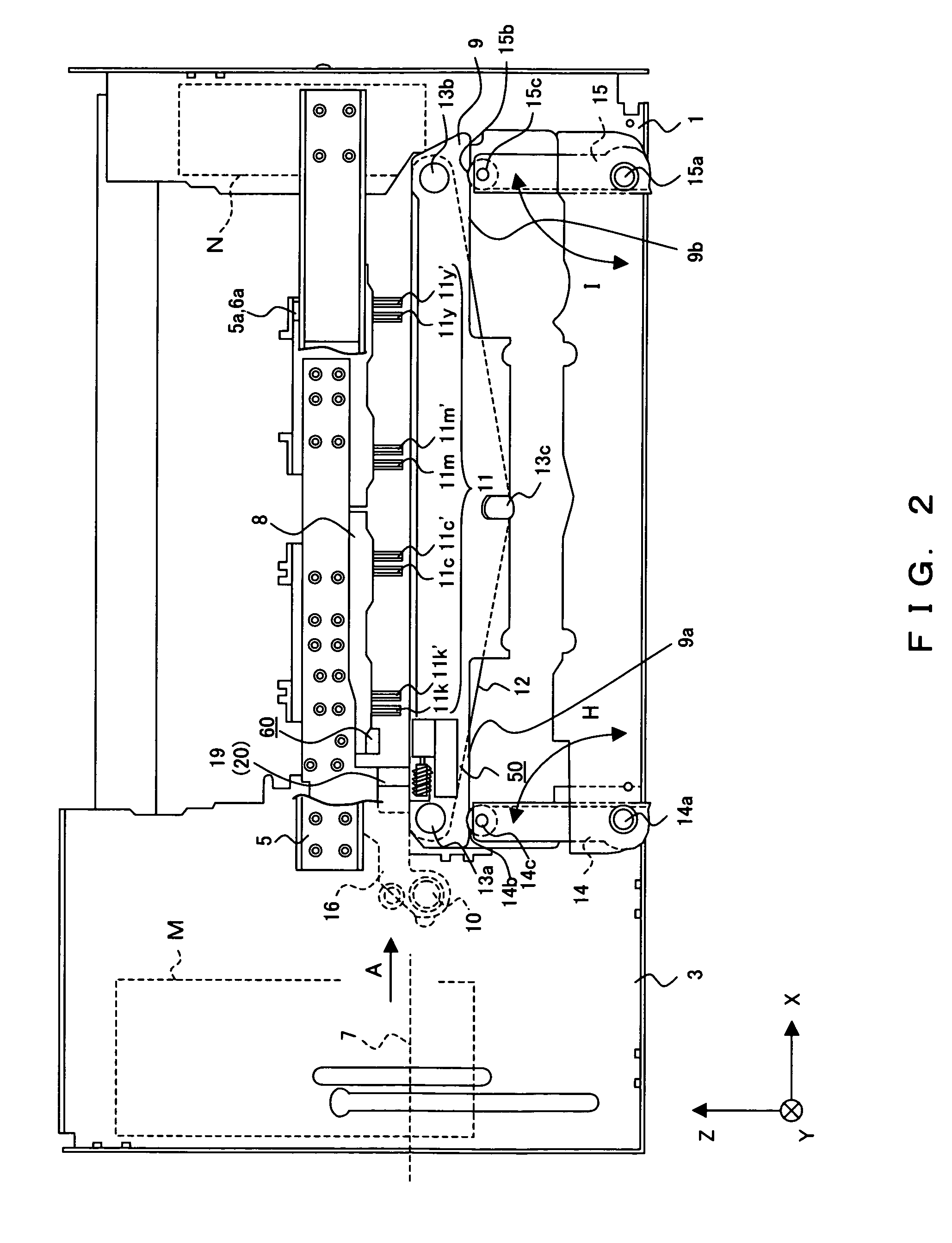
[0064]FIGS. 2 and 3 are each a configuration diagram of a positioning structure of an image forming apparatus. FIG. 2 is a side view of an image forming apparatus used by the present invention. FIG. 3 is a plan view showing a carriage, and a frame and surrounding area.
[0065]The image forming apparatus adopts an inkjet system. In the image forming apparatus of the inkjet system, the definitions are: an X axis direction (i.e., second scan direction) for the transport direction of a recording medium 7; a Y axis direction (i.e., first scan direction) for the direction of the width of the recording medium 7, which is perpendicular to the X axis direction; and a Z axis direction (i.e., the up and down direction) for the ...
second embodiment
[0128]The following description deals with a second embodiment according to the present invention. Note that the following description omits parts of the same comprisal as those of the first embodiment and only concerns those parts that are different.
[0129]The present embodiment uses sensors 70A and 70B as shown by FIG. 12; and is configured to place an LED 71 on the belt platen 9 and places on the carriage 8 a light receiving element 72 whose light receiving surface is divided into four parts in parallel with the X and Y axis directions as shown by FIG. 13, instead of not using the reflection target. Each light receiving surface is separately disposed by c1, c2, c3 and c4 as light receiving elements 72 of the sensor 70A; and is separately disposed by d1, d2, d3 and d4 as light receiving elements 72 of the sensor 70B.
[0130]Each of the light receiving surfaces c1 through c4, and d1 through d4, outputs each electric signal c1e, c2e, c3e, c4e, d1e, d2e, d3e and d4e respectively by rece...
third embodiment
[0139]The next description is of a third embodiment according to the present invention by referring to FIGS. 14 and 15. Note that the following description omits parts of the same comprisal as the first embodiment and only describes those parts that are different.
[0140]FIGS. 14 and 15 show a positional relationship of a magnet 81, i.e., a magnetic member, and each Hall element (i.e., magnetic sensor). Each of sensors 80A and 80B is constituted by one magnet 81 placed on the belt platen 9 and two Hall elements 82a and 82b, or two Hall elements 83a and 83b, respectively, which are placed on the carriage 8 and arrayed in the X axis direction. And an inclination is detected by utilizing a difference in the magnetic field distribution of the magnet 81 at the positions of respective Hall elements.
[0141]Specifically, each of the Hall elements 82a (i.e., x1 position) and 82b (i.e., x2 position), and 83a (i.e., x1 position) and 83b (i.e., x2 position), is respectively placed at the positions...
PUM
 Abstract
Description
Claims
Application Information
 - R&D
- Intellectual Property
- Life Sciences
- Materials
- Tech Scout
- Unparalleled Data Quality
- Higher Quality Content
- 60% Fewer Hallucinations
Browse by: Latest US Patents, China's latest patents, Technical Efficacy Thesaurus, Application Domain, Technology Topic, Popular Technical Reports.
© 2025 PatSnap. All rights reserved.Legal|Privacy policy|Modern Slavery Act Transparency Statement|Sitemap|About US| Contact US: help@patsnap.com


