Eureka AIR delivers breakthrough ideas for toughest innovation challenges, trusted by R&D personnel around the world.

Printer and printing method which prevents a decurling unit from deteriorating a print quality

a printing method and printing method technology, applied in printing, instruments, measurement devices, etc., can solve the problems of excessive decurling, and crease at the portion, so as to prevent the deterioration of print quality

Inactive Publication Date: 2013-09-24
CANON KK
View PDF11 Cites 1 Cited by
  • Summary
  • Abstract
  • Description
  • Claims
  • Application Information

AI Technical Summary

Benefits of technology

[0009]The present invention is directed to provide a printer and a printing method that prevent the deterioration in print quality without adding a mechanism in a case of printing in which a plurality of inks thermally adheres to a roll recording medium with heat.

Problems solved by technology

However, when the raised member keeps in contact with the same portion of the recording medium for a longtime, a crease is produced at the portion.
Since there is a high possibility that ink does not normally adhere to the portion of the crease production, a problem of deterioration in print quality can arise.
Therefore, by actively pressing the portion heated by the thermal head to the raised member, excessive decurling can produce a crease at the portion.
If the crease is made in a print area (area in which a large part of an image is printed) on the recording medium, a problem of deterioration in print quality can occur.
However, to add the mechanism, the installing space of the mechanism needs to be secured, and the size of printer therefore increases and product costs rise.

Method used


Image

  • Printer and printing method which prevents a decurling unit from deteriorating a print quality
  • Printer and printing method which prevents a decurling unit from deteriorating a print quality
  • Printer and printing method which prevents a decurling unit from deteriorating a print quality

Examples


Embodiment Construction

[0038]Various exemplary embodiments, features, and aspects of the invention will be described in detail below with reference to the drawings.

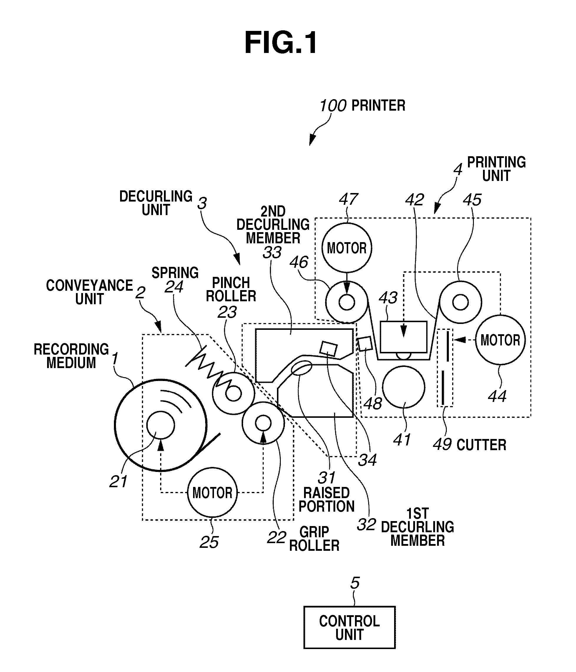
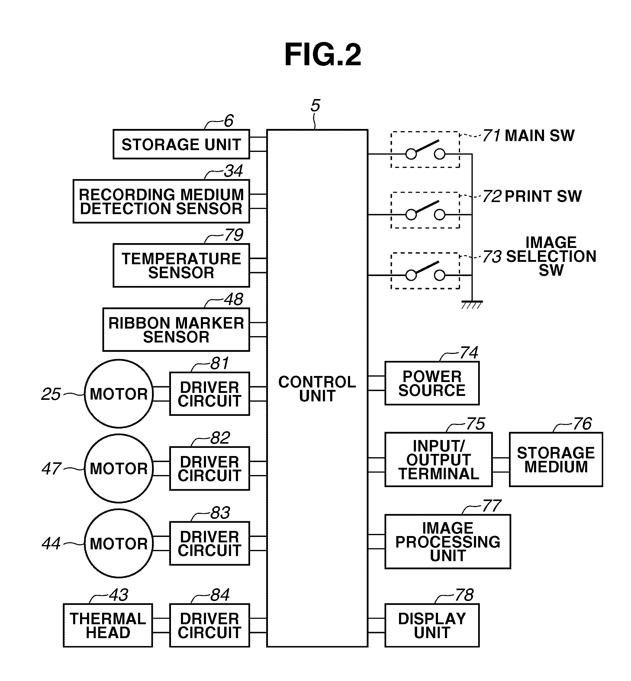
[0039]FIG. 1 illustrates a configuration of a printer according to a first exemplary embodiment. Referring to FIG. 1, a printer 100 according to the first exemplary embodiment has one printing target range by separating a roll recording medium 1 in the length direction, and includes: conveyance unit 2; decurling unit 3; print unit 4; and control unit 5. In the printer 100, the control unit 5 controls operation of the conveyance unit 2 and the print unit 4, thereby printing the data in the printing target range of the recording medium 1 that has passed through the decurling unit 3. Hereinbelow, a description is given of a specific configuration of the conveyance unit 2, the decurling unit 3, the print unit 4, and the control unit 5.

[0040]In the conveyance unit 2, the recording medium 1 is wound like a roll to a core portion 21 (refer to FIG. 1)....

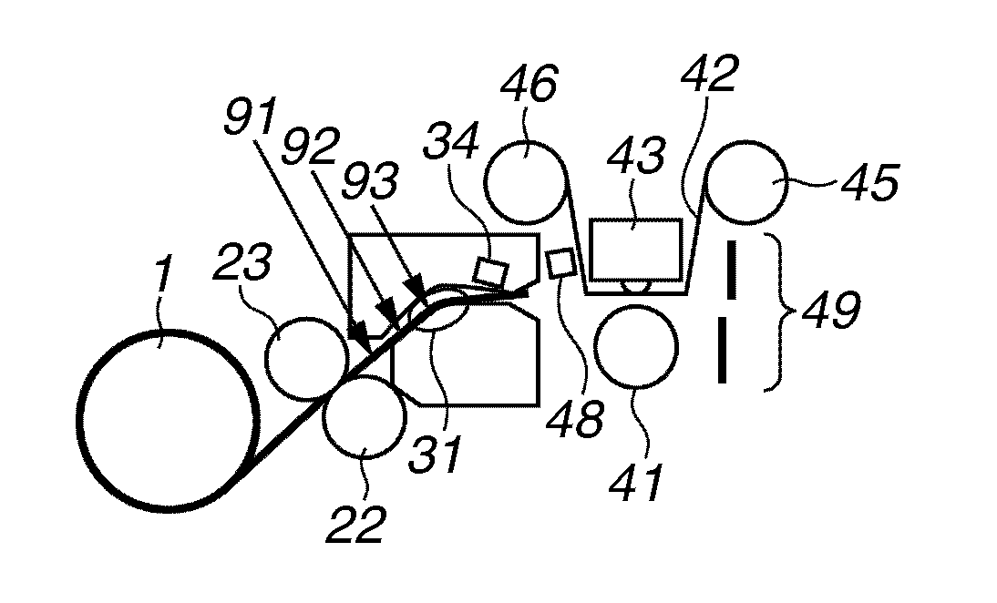

PUM


Abstract

A printer is provided that includes a conveyance unit configured to nip and simultaneously convey the roll recording medium; a print unit configured to print an image by sequentially transferring a plurality of color inks on the recording medium while nipping the recording medium conveyed by the conveyance unit; a decurling unit disposed between the conveyance unit and the print unit, and configured to include a raised portion that decurls the recording medium by contacting the recording medium conveyed by the conveyance unit; and a control unit configured to control the conveyance unit to convey the recording medium to a waiting position after ending the transfer of one color ink, wherein the waiting position is a position where an area on a leading edge side of the recording medium is in contact with the raised portion.

Description

BACKGROUND OF THE INVENTION[0001]1. Field of the Invention[0002]The present invention relates to a printer and a printing method that decurl a recording medium.[0003]2. Description of the Related Art[0004]A printer that prints data onto a roll recording medium includes a decurling mechanism that decurls a recording medium. The decurling mechanism decurls the recording medium to inversely curl the recording medium by moving and pressing a raised member to the recording medium or pressing the recording medium to the raised member.[0005]However, when the raised member keeps in contact with the same portion of the recording medium for a longtime, a crease is produced at the portion. Since there is a high possibility that ink does not normally adhere to the portion of the crease production, a problem of deterioration in print quality can arise. Japanese Patent Publication No. 3190489 discusses an apparatus that solves the problem. A decurling apparatus discussed in Japanese Patent Public...

Claims


Application Information

Patent Timeline
Patent Type & Authority Patents(United States)
IPC IPC(8): B41J15/00B41J2/315B41J35/16
CPCB41J15/04B41J11/0005
Inventor OKUNO, RYOJI
Owner CANON KK
Why Eureka
Eureka Blog
Learn More