
Method and arrangement for demodulating an optical DPSK binary signal

a technology of binary signal and optical dpsk, which is applied in the direction of electromagnetic transmission, electrical apparatus, transmission, etc., can solve the problems of reducing the capacity and therefore reducing the efficiency of a transmission system, and prone to interference. , to achieve the effect of improving transmission modulation, less interference, and improving transmission efficiency

Inactive Publication Date: 2010-11-02
XIEON NETWORKS SARL
View PDF14 Cites 2 Cited by
  • Summary
  • Abstract
  • Description
  • Claims
  • Application Information

AI Technical Summary

Benefits of technology

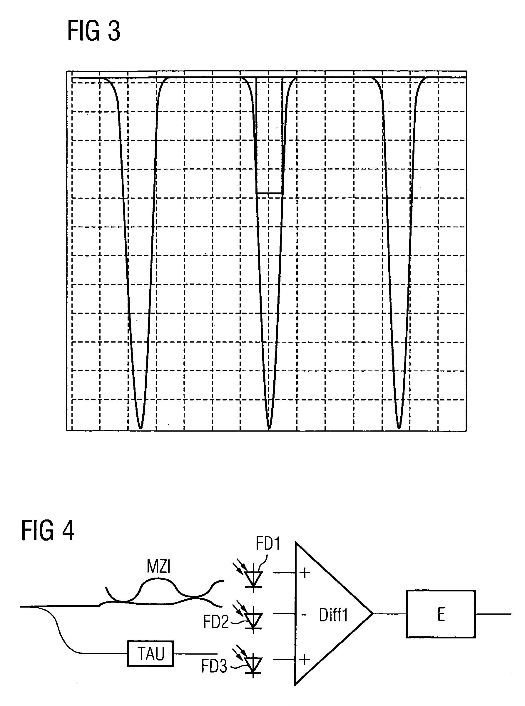
[0011]The advantage of the invention is that the receiver for demodulating the DPSK binary signal, which therefore determines phase information, additionally detects amplitude information also, i.e. detects the amplitude dip using an amplitude demodulator, and evaluates the phase and amplitude information. This evaluation can be performed by combining and / or jointly evaluating the phase and amplitude information or alternatively exclusively evaluating or using one of the two, e.g. the information with the lower bit error rate which is determined e.g. on the basis of the number of errors to be corrected by forward error correction, or FEC for short. By evaluating the amplitude information contained in the DPSK signal, which contains exactly the same information as the phase, as an amplitude dip occurs at each phase shift, redundancy information is available. As the amplitude is frequently less prone to interference due to cross phase modulation than the phase, improved modulation of the transmitted information as well as improved transmission can thus be achieved. By evaluating both phase and amplitude information in the optical DPSK binary signal, an increase in transmission robustness to interference, particularly cross phase modulation, can be achieved.
[0012]Advantageous embodiments of the invention are set forth in the dependent claims and in the exemplary embodiment.

Problems solved by technology

A known problem of phase modulation methods, particularly in optical transmission systems, is their sensitivity to interference caused by cross phase modulation, or XPM for short.
This can be so severe that error-free reception of the DPSK channel is not possible using the method outlined above.
This has reduced the capacity and therefore the efficiency of a transmission system.

Method used


Image

  • Method and arrangement for demodulating an optical DPSK binary signal
  • Method and arrangement for demodulating an optical DPSK binary signal
  • Method and arrangement for demodulating an optical DPSK binary signal

Examples


Embodiment Construction

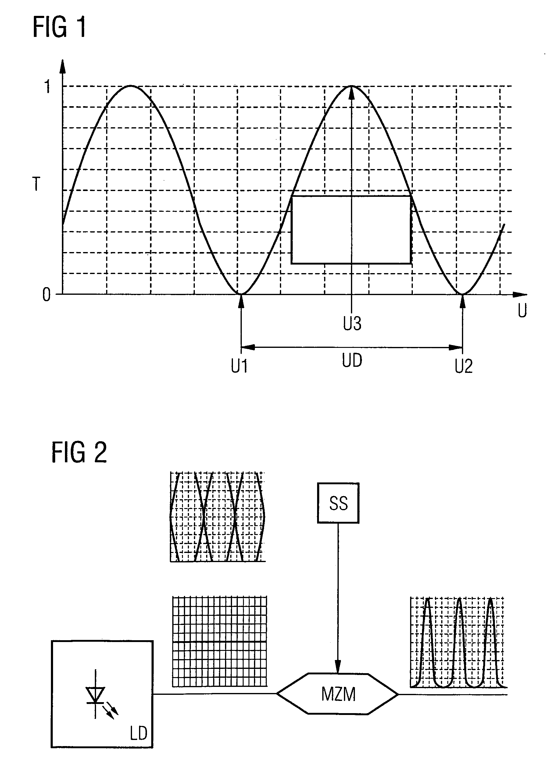
[0023]FIG. 1 shows a plot of a transmission characteristic of a Mach-Zehnder modulator MZM. A voltage U is plotted on the horizontal axis and the transmission T on the vertical axis of the graph. The transmission T has a value range between the 0 and 1, i.e. at 0 there is no transmission and at 1 complete transmission of an optical signal passing through the Mach-Zehnder modulator MZM. A Mach-Zehnder modulator MZM has a sinusoidal transmission characteristic (periodic response) which is frequency-dependent. At a first voltage or rather a first voltage value U1 and at a second voltage or rather a second voltage value U2, transmission is maximal and attains the value 1 in the optimum case. At a third voltage U3, which is approximately in the middle or approximately midway between the first and second voltage U1, U2, transmission is minimal and attains the value 0 in the ideal case.

[0024]FIG. 2 shows an arrangement comprising an optical carrier signal source LD such as a laser diode, w...


PUM


Abstract

An optical differentially phase shift keyed or DPSK binary signal which in the event of phase changes exhibits amplitude reductions and is phase-demodulated is provided. The received optical DPSK binary signal is additionally amplitude-demodulated and resulting phase and amplitude information is evaluated.

Description

CROSS REFERENCE TO RELATED APPLICATIONS[0001]This application claims priority of German application No. 102005041368.4 DE filed Aug. 31, 2005, which is incorporated by reference herein in its entirety.FIELD OF INVENTION[0002]The invention relates to a method and an arrangement for demodulating an optical DPSK binary signal.BACKGROUND OF INVENTION[0003]There are different modulation methods for transmitting data. One possible modulation scheme, particularly in optical data transmission systems, is known as differential phase shift keying, or DPSK for short, whereby the information is encoded in the phase difference between two consecutive bits of a data signal. One possible implementation is to leave the phase of the subsequent bit the same if a logical “one” is to be transmitted and to change it by 180° if a logical “zero” is to be transmitted or vice versa.[0004]To receive and convert the phase information into receiver-end amplitude information, i.e. to recover the data signal, in...

Claims


Application Information

Patent Timeline
Patent Type & Authority Patents(United States)
IPC IPC(8): H04B10/04H04B10/66
CPCH04B10/66
Inventor SCHAIRER, WOLFGANGWEISKE, CLAUS-JORG
Owner XIEON NETWORKS SARL
Learn More