
Mounting bracket

a technology for mounting brackets and televisions, which is applied in the direction of machine supports, instruments, and electrical apparatus casings/cabinets/drawers, etc., can solve the problems of reducing the likelihood causing significant damage, and/or bodily injury, and reducing the likelihood of flat-panel televisions falling and causing significant damage. , the effect of reducing the likelihood of falling and causing significant damag

Active Publication Date: 2010-11-02
PEERLESS INDS
View PDF16 Cites 17 Cited by
  • Summary
  • Abstract
  • Description
  • Claims
  • Application Information

AI Technical Summary

Benefits of technology

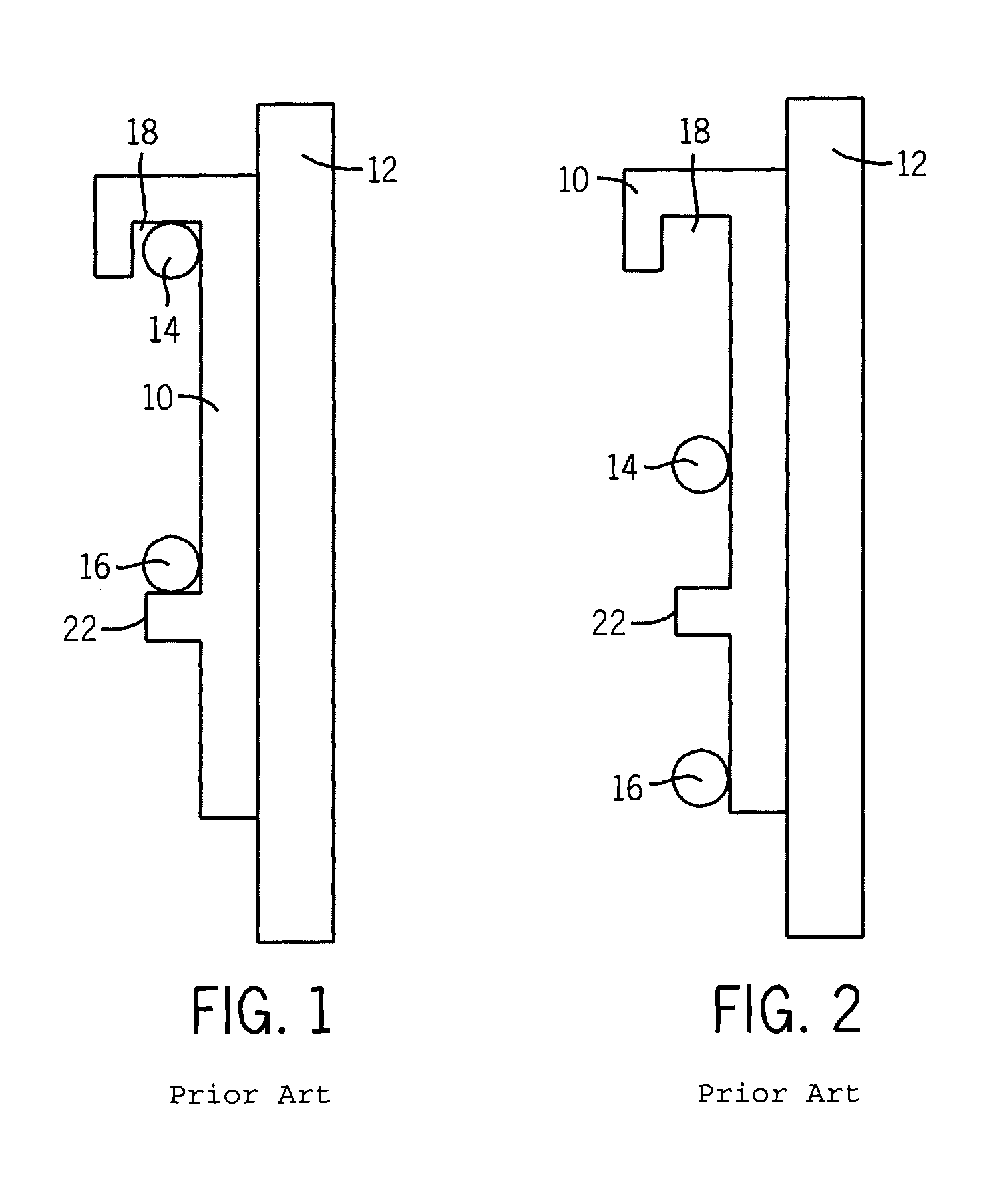
[0010]With the present invention, the possibility of a mounting bracket being misaligned relative to the retaining portions is greatly reduced. As a result, the likelihood of a flat panel television falling and causing significant damage and / or bodily injury is also diminished.

Problems solved by technology

As a result, the likelihood of a flat panel television falling and causing significant damage and / or bodily injury is also diminished.

Method used


Image

  • Mounting bracket
  • Mounting bracket
  • Mounting bracket

Examples


second embodiment

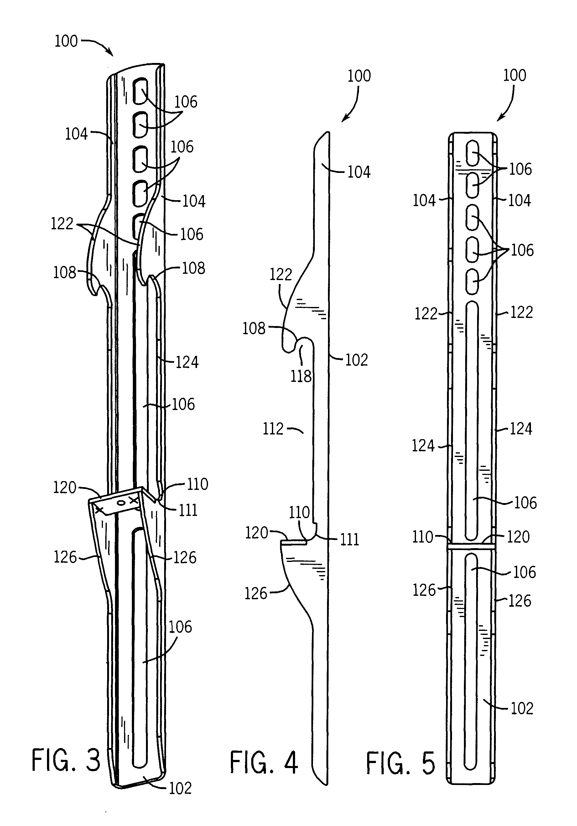
[0036]FIG. 8 shows a mounting bracket 300 constructed in accordance with the present invention. The mounting bracket 300 of FIG. 8 is similar to the mounting bracket 100 of FIGS. 3-7. However, the mounting bracket 300 of FIG. 8 includes a substantially larger mounting contact portion 102 than that shown in FIGS. 3-7. Additionally, it should be noted that the upper and lower ramping surfaces 122 and 126 are substantially straight in nature and include no substantial curvature.

third embodiment

[0037]FIG. 9 shows a mounting bracket 400 constructed in accordance with the present invention. Unlike the embodiments shown in FIGS. 3-8, the mounting bracket 400 of FIG. 9 does not include any side portions whatsoever. Instead, the upper and lower ramping surfaces 122 and 126 are formed directly out of the top and bottom of the mounting contact portion 102. It should be noted that the upper and lower ramping surfaces 122 and 126 can also be formed from separate components which are then coupled to the mounting contact portion 102.

[0038]FIG. 10 shows a mounting system 500 constructed according to still another embodiment of the present invention. the mounting system 500 of FIG. 10 includes a screen mounting plate 502 that is used to couple a display unit 504 to an interface assembly 506. The interface assembly 506 includes upper ramps 122 and lower ramps 126 as discussed above, and is also configured to attach to a wall plate 508 which attaches to a wall (not shown). In this embodi...


PUM

PropertyMeasurementUnit
lengthaaaaaaaaaa
distanceaaaaaaaaaa
thicknessaaaaaaaaaa

Abstract

An improved mounting bracket that provides an indication to an installer when a mount is not correctly aligned. The mounting bracket comprises a mounting contact portion and at least one side portion integrally connected to the mounting contact portion, with the at least one side portion defining a receiving region for accepting one or more retaining portions of a mount. The at least one side portion includes a first ramped surface at least partially outside of the receiving region. The first ramped surface configured to contact a retaining portion when the retaining portion is misaligned with the receiving region, thereby informing an installer of the misalignment.

Description

CROSS-REFERENCE TO RELATED APPLICATIONS[0001]The present application claims priority to U.S. Provisional Patent Application No. 60 / 727,105, filed Oct. 14, 2005 and incorporated herein by reference in its entirety.FIELD OF THE INVENTION[0002]The present invention relates generally to mounting brackets. More particularly, the present invention relates to brackets that are used in conjunction with systems for mounting devices such as flat panel televisions.BACKGROUND OF THE INVENTION[0003]In recent years, flat-panel televisions have become enormously popular in both the commercial and the residential sectors. As the prices for plasma and liquid crystal display (LCD) flat panel displays have continued to fall, and as the quality for the same devices have improved, more and more business and individuals have purchased such devices both for business and home entertainment purposes.[0004]One of the advantages of flat-panel television units that customers have found particular appealing is ...

Claims


Application Information

Patent Timeline
Patent Type & Authority Patents(United States)
IPC IPC(8): E04G3/00
CPCF16M11/10F16M13/02Y10S248/923F16M2200/022Y10S248/921Y10T29/49826H05K7/16
Inventor LAM, WILLIAM PHUONGO'KEENE, DUGANMONACO, GARRY
Owner PEERLESS INDS
Learn More