Electronic device control apparatus, method for controlling electronic device, electronic device control program, and computer-readable recording medium having recorded electronic device control program

a technology of electronic devices and control apparatuses, applied in the direction of electric controllers, electric programme control, instruments, etc., can solve the problem of not being able to enable diverse control for each user, and achieve the effect of ease and precision

Active Publication Date: 2010-10-26
PANASONIC CORP
View PDF10 Cites 1 Cited by
  • Summary
  • Abstract
  • Description
  • Claims
  • Application Information

AI Technical Summary

Benefits of technology

[0007]The invention is to solve the problems in the related art as discussed above, and therefore has an object to provide an electronic device control apparatus, a method for controlling an electronic device, an electronic device control program, and a computer-readable recording medium having recorded an electronic device control program for achieving the settings to enable associated control that suits the life pattern of the user and the characteristics of connected electronic devices with ease and precision.
[0013]Hence, according to the invention, by generating information about the condition and the control to enable the associated control according to the operational statuses of the home appliances actually used in the house, it is possible to enable the associated control that suits the life pattern of the user and the characteristics of the connected electronic devices, which makes it possible to make the settings precisely so as not to cause inconsistency in the condition and the operations of the associated control. In addition, because information about the condition and the control to enable the associated control is automatically generated by using the operational status link information to extract the information for the associated control, the user or the system constructor is able to make the settings of the associated control with ease without having to perform operations.

Problems solved by technology

The method in the related art involving the sequential operations on home appliances, however, has problems in that it is necessary to determine in advance which appliance is to be placed under associated control and in which manner before the operations, a setting constructor has to consider associated control to enable the control that suits the life pattern of the user, and further, when he makes an error during the operations, he has to perform the operations again.
This method, therefore, has a problem that it is not suitable to enable diverse control for each user.Patent Document 1: Japanese Patent No. 2916020Patent Document 2: JP-A-2003-274033

Method used


Image

  • Electronic device control apparatus, method for controlling electronic device, electronic device control program, and computer-readable recording medium having recorded electronic device control program
  • Electronic device control apparatus, method for controlling electronic device, electronic device control program, and computer-readable recording medium having recorded electronic device control program
  • Electronic device control apparatus, method for controlling electronic device, electronic device control program, and computer-readable recording medium having recorded electronic device control program

Examples


first embodiment

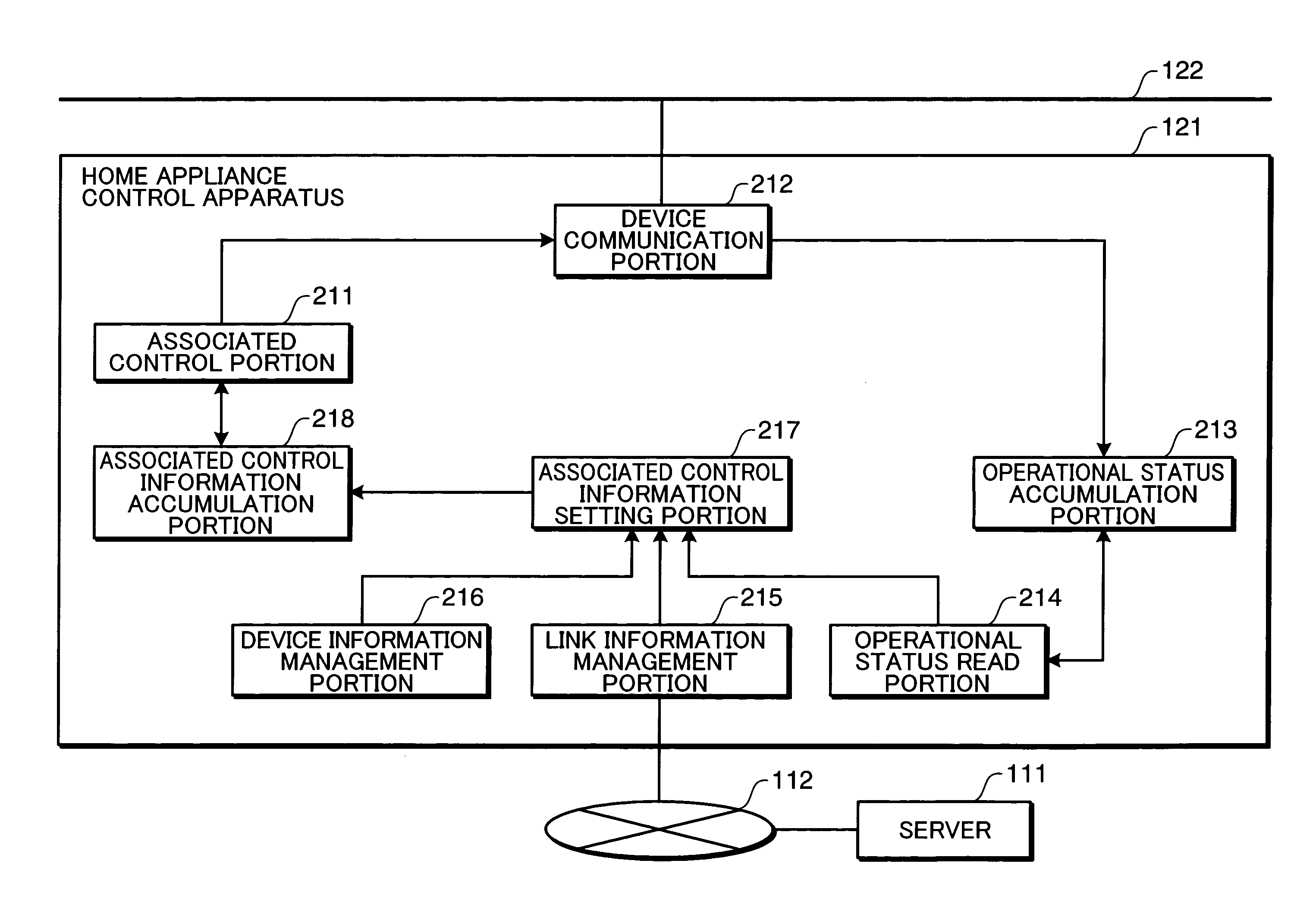
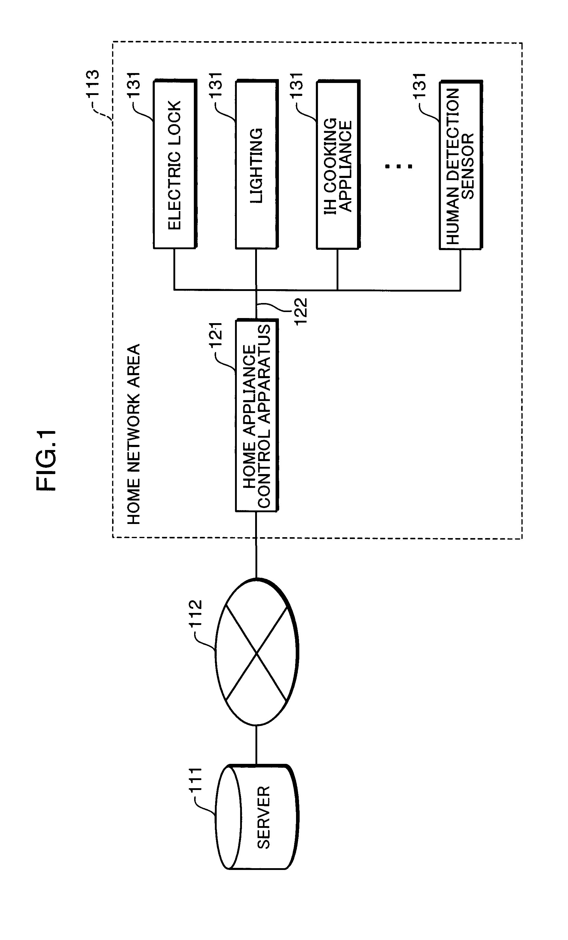
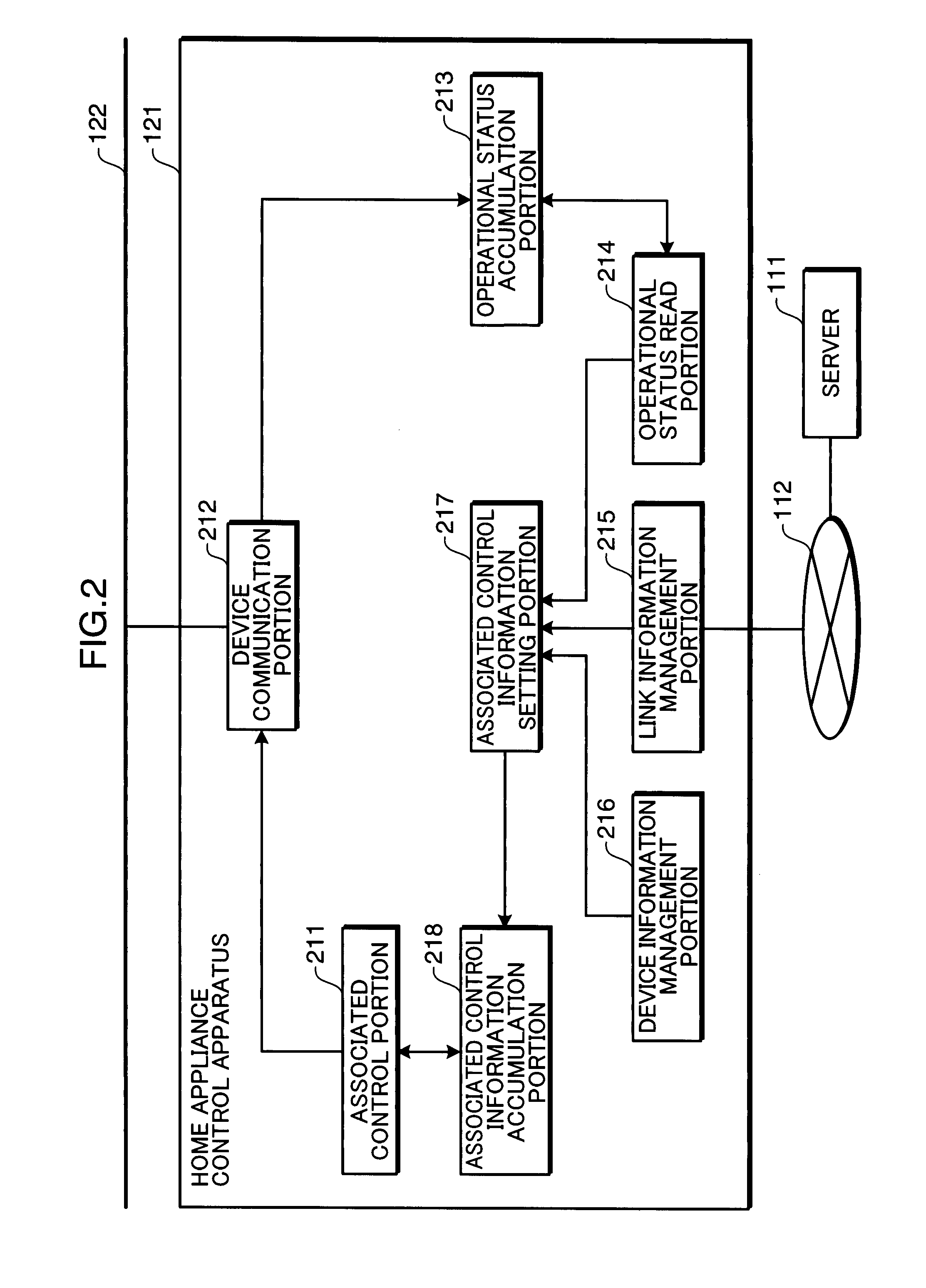
[0044]FIG. 1 is a view showing the configuration of a home network system according to one embodiment of the invention. In a home network area 113, plural network home appliances (hereinafter, referred to also as home appliances or devices) 131 are connected to a home network 122, and a home appliance control apparatus 121 that controls these network home appliances 131 is also connected thereto. In addition, an outside server 111 is connected to the home appliance control apparatus 121 via an outside network 112.

[0045]The home appliances 131 are, for example, electric locks, lights, IH (Induction Heating) cooking appliances, human detection sensors, and so forth. In this embodiment, besides the home appliances, devices, such as sensors and meters that measure and detect the house equipment and the living environments (for example, the gas meter, the water meter, the electric power meter, etc.), may be connected to the home network 122.

[0046]The outside network 112 is an outside com...

second embodiment

[0085]A second embodiment to designate the function of the device without designating the device type as the operational status link information will now be described.

[0086]FIG. 14 is a view showing one example of the device type information. The device type information shown in FIG. 14 comprises plural device types and functions furnished to the respective device types. In FIG. 14, the device type is brought into a correspondence with plural functions: function 1, function 2, and function 3. FIG. 15 is a view showing one example of the operational status link information in which the function is designated. In the trigger device information and the linked device information in the operational status link information shown in FIG. 15, the function furnished to the device is stored instead of the device type. FIG. 16 is a view showing one example of the associated control information in which the function is designated. In the condition data and the control data in the associated con...

third embodiment

[0092]A third embodiment to designate the device that performs the condition judgment besides the trigger device will now be described.

[0093]FIG. 18 is a view showing one example of the operational status link information containing status confirming device information. The operational status link information shown in FIG. 18 contains status confirming device information besides the trigger device information, the linked device information, and the link interval information. The status confirming device information contains information about the device type and the installed location of a status confirming device, which is a device whose operational status is confirmed when the operational status of the trigger device has changed, and the property specifying the type of operational status to be confirmed and the property value indicating the value of the property. FIG. 19 is a view showing one example of intermediate data in which the extraction condition and the extracted data are ...


PUM


Abstract

A device communication portion receives operational status data, and an operational status accumulation portion accumulates the operational status data. A link information management portion manages operational status link information containing trigger device information to specify the operational status of a single home appliance among plural home appliances and linked device information to specify another home appliance that activates in association with the operational status of the single home appliance. An operational status read portion extracts operational status data corresponding to the operational status in the trigger device information and extracts operational status data corresponding to the linked device information. An associated control information setting portion generates associated control information containing the operational status of the single home appliance and used as the condition to start the associated control of a single electronic device and another electronic device and the content of control on the another home appliance.

Description

TECHNICAL FIELD[0001]The present invention relates to an electronic device control apparatus, a method for controlling an electronic device, an electronic device control program, and a computer-readable recording medium having recorded an electronic device control program for managing and controlling the status of an electronic device, and more particularly, to an electronic device control apparatus, a method for controlling an electronic device, an electronic device control program, and a computer-readable recording medium having recorded an electronic device control program for enabling associated control of another electronic device upon a change of the operational status of a given electronic device as a trigger.BACKGROUND ART[0002]Regarding a method for setting associated control of home appliances, as a pattern setting method to control home appliances upon a button operation on a home appliance control apparatus as a trigger, there has been used a method for making the settin...

Claims


Application Information

Patent Timeline
Patent Type & Authority Patents(United States)
IPC IPC(8): G05B19/18G05B11/01G06F15/16
CPCG05B15/02G08C17/00G05B2219/2642G08C2201/50
Inventor SHIMBA, NORIKONAGAMITSU, SACHIO
Owner PANASONIC CORP
Why Eureka
Try Eureka