Angle-adjustable mounting apparatus

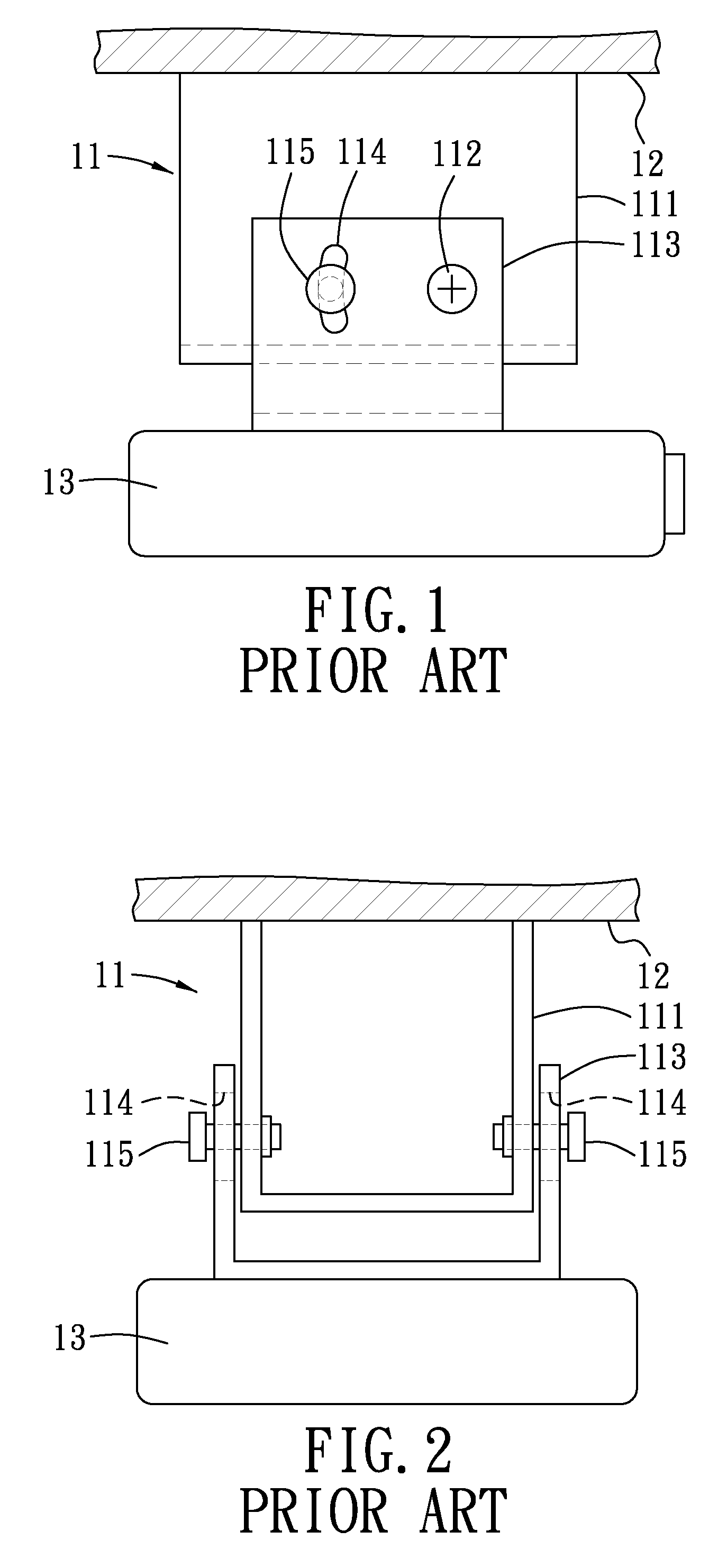
a technology of mounting apparatus and angle adjustment, which is applied in the direction of machine supports, building scaffolds, other domestic objects, etc., can solve the problems of quite strenuous process of adjusting the angle of the electronic device b>13/b>, and achieve the effect of precision and eas

Active Publication Date: 2013-09-19
HUANG MING HSIEN
View PDF18 Cites 2 Cited by
  • Summary
  • Abstract
  • Description
  • Claims
  • Application Information

AI Technical Summary

Benefits of technology

[0009]Therefore, an object of the present invention is to provide an angle-adjustable mounting apparatus which may be adjusted with precision and ease.
[0016]Preferably, the second mounting device includes a first connection part, a second connection part, and a third pivot-control unit. The first connection part is connected pivotally to the second mounting part. The second connection part is to be connected to the second object and is retained pivotally on the first connection part so as to be pivotable relative to the first connection part about a third axis perpendicular to the first and second axes. The third pivot-control unit includes an adjusting base and a third adjusting rod. The adjusting base is provided on the second connection part and is formed with a third threaded hole therethrough. The third threaded hole has a hole axis that is not parallel to the third axis. The third adjusting rod is a threaded rod coupled rotatably to the first connection part for rotation about a rod axis of the third adjusting rod. The third adjusting rod threadedly engages the third threaded hole. Rotation of the third adjusting rod relative to the first connection part results in displacement of the adjusting base along the third adjusting rod and pivoting of the second connection part relative to the first connection part.
[0017]Effects of the present invention reside in that the first and second mounting devices are to be coupled respectively to the first and second objects, and the second mounting device is connected pivotally to the first mounting device, such that by means of cooperative designs, such as pivotal connection between the first and second mounting devices, rotation of the first adjusting rod, and linear displacement between the second component and the first adjusting rod, an angle between the first and second objects may be adjusted with precision and ease.

Problems solved by technology

Therefore, the process of adjusting the angle of the electronic device 13 is quite strenuous.

Method used


Image

  • Angle-adjustable mounting apparatus
  • Angle-adjustable mounting apparatus
  • Angle-adjustable mounting apparatus

Examples


Embodiment Construction

[0036]Before the present invention is described in greater detail with reference to the embodiments, it should be noted that the same reference numerals are used to denote the same elements throughout the following description.

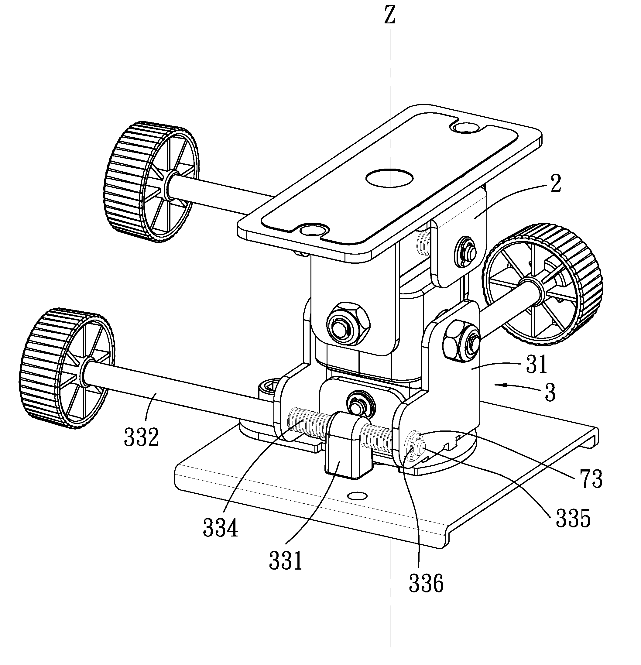
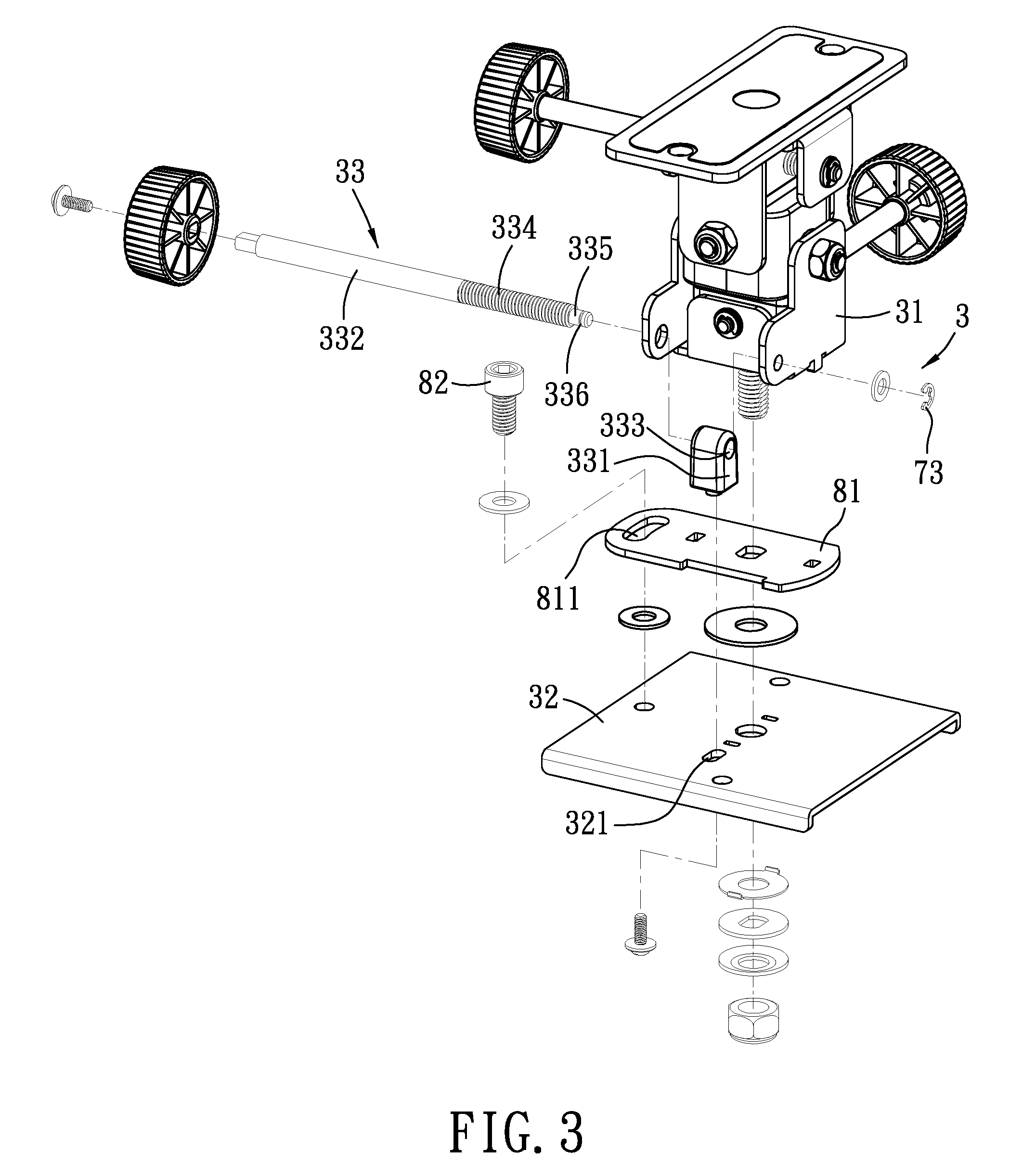
[0037]Referring to FIG. 3 and FIG. 4, a first preferred embodiment of an angle-adjustable mounting apparatus according to the present invention is for mounting a second object, such as a base of a projector (not shown), to a first object, such as a telescopic rod fixed to a wall (not shown). Components of the angle-adjustable mounting apparatus are pivotable about a first axis (X), a second axis (Y) and a third axis (Z) which are perpendicular to each other such that a relative position of the second object with respect to the first object may be adjusted in three directions.

[0038]Pivoting of the components of the angle-adjustable mounting apparatus about the first axis (X) is illustrated hereinafter.

[0039]Referring to FIGS. 4, 5 and 6, the first preferred emb...


PUM


Abstract

An angle-adjustable mounting apparatus is for mounting a second object to a first object, and includes a first mounting device to be coupled to the first object, a second mounting device to be coupled to the second object and connected pivotally to the first mounting device, and a pivot-control unit. The pivot-control unit includes a plug component with a curved surface, a socket component which abuts against and is rotatable relative to the plug component to enable the second mounting device to pivot relative to the first mounting device, and an adjusting rod coupled to the socket component and operable to drive the socket component so that assembly of the socket component and the second mounting device pivots relative to the plug component.

Description

CROSS-REFERENCE TO RELATED APPLICATION[0001]This application claims priority of Taiwanese Patent Application No. 101204856, filed on Mar. 16, 2012.BACKGROUND OF THE INVENTION[0002]1. Field of the Invention[0003]The present invention relates to an angle-adjustable mounting apparatus, more particularly to an angle-adjustable mounting apparatus which may be adjusted with precision and ease.[0004]2. Description of the Related Art[0005]Referring to FIG. 1 and FIG. 2, a conventional mounting apparatus 11 is adapted for mounting an electronic device 13 to a fixed object, such as a ceiling 12. The mounting apparatus 11 includes a first mounting device 111 which is to be fixed to the ceiling 12, a second mounting device 113 which is for mounting the electronic device 13 and which has two lateral wings disposed at two sides of the first mounting device 111, and two pins 112 which are respectively disposed through the two lateral wings of the second mounting device 113 and the two sides of the...

Claims


Application Information

Patent Timeline
Patent Type & Authority Applications(United States)
IPC IPC(8): F16M13/02
CPCF16M11/08F16M13/02F16M11/2057F16M11/18
Inventor HUANG, MING-HSIEN
Owner HUANG MING HSIEN
Why Eureka
Try Eureka