
Manipulator with multiple degrees of freedom

a manipulator and freedom technology, applied in the field of manipulators with multiple degrees of freedom, can solve the problems that the forceps used in minimally invasive surgery do not allow an approach to a diseased part from a limited direction, and achieve the effects of increasing stability of motion, reducing transmission loss of drive power, and raising durability and control accuracy

Active Publication Date: 2010-10-26
MITSUISHI MAMORU +1
View PDF9 Cites 380 Cited by
  • Summary
  • Abstract
  • Description
  • Claims
  • Application Information

AI Technical Summary

Benefits of technology

The present invention provides a manipulator with multiple degrees of freedom for surgery that is durable, has high control accuracy, and is easy to sterilize and clean. The manipulator has at least three degrees of freedom including relative opening / closing of a pair of gripping members, rotation of both gripping members around a first axis, and rotation of both gripping members around a second axis. The driving means of the manipulator uses a link mechanism that converts the drive power to the rotation of the gripping members. The link mechanism is stable and has high transmission power, reducing the need for a separate wire. The manipulator is easy to sterilize and clean and can be attached and detached from the driving means easily. The link mechanism is stable and improves the stability of motion of the gripping member. The dimensions and arrangement of the components are set up so that the axial line of the second axis is perpendicular to the third link when the first link, second link, and third link are arranged in line. This structure ensures that an intersection between virtual extensions exists on the axial line of the second axis when the first supporting body is bent.

Problems solved by technology

The forceps used in the minimally invasive surgery does not allow an approach to a diseased part but from a limited direction because its posture is restricted by the incised hole.

Method used


Image

  • Manipulator with multiple degrees of freedom
  • Manipulator with multiple degrees of freedom
  • Manipulator with multiple degrees of freedom

Examples


Embodiment Construction

[0043]Hereinafter, preferred embodiments (implementations) of the present invention will be described in detail by way of example with reference to accompanying drawings.

(Configuration of Bending Forceps System)

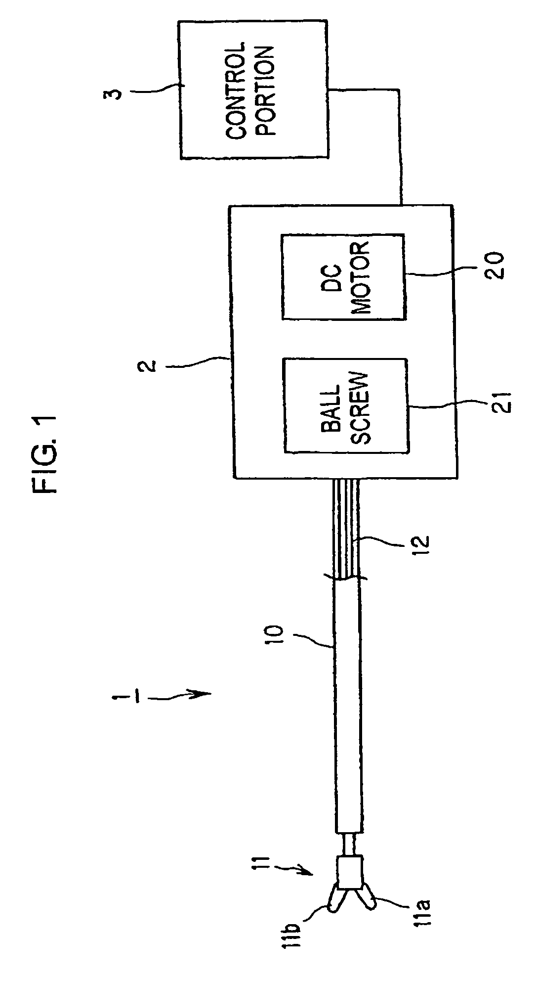
[0044]FIG. 1 shows a bending forceps system including a manipulator with multiple degrees of freedom according to an implementation of the present invention.

[0045]The bending forceps system comprises a bending forceps 1 which is a manipulator with multiple degrees of freedom, an actuator 2 which is a driving means for driving the bending forceps 1 and a control portion 3 for controlling the actuator 2. This bending forceps system is used for minimally invasive surgery such as abdominal cavity surgery and the like.

[0046]The bending forceps 1 generally comprises an arm portion 10 to be attached to the actuator 2 and a gripping portion 11 provided at the front end of the arm portion 10. The gripping portion 11 is provided with a pair of gripping members 11a, 11b which can be ope...


PUM


Abstract

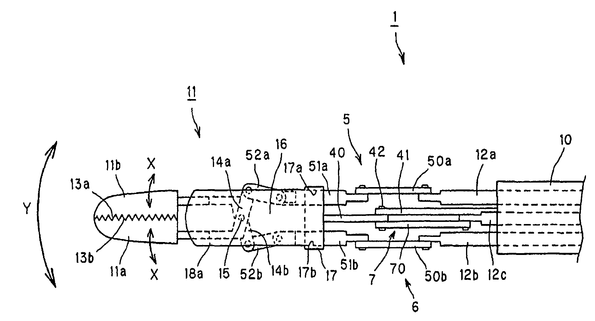
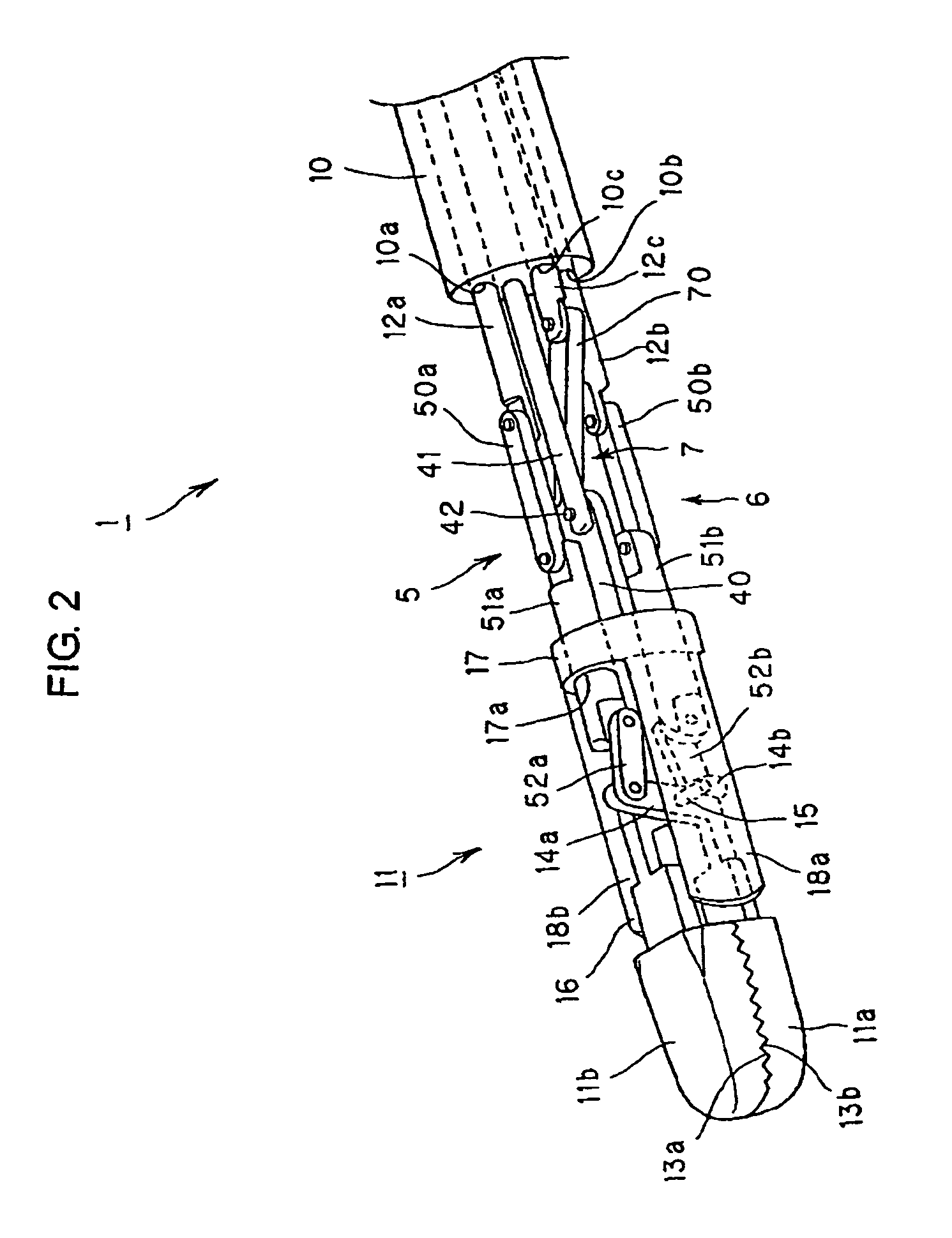
A bending forceps 1 has at least three degrees of freedom including relative opening / closing of a pair of gripping members 11a, 11b, rotation of both the gripping members around a first axis 15 and rotation of both the gripping members around a second axis 42 existing on an imaginary plane substantially perpendicular to the first axis 15. A drive power from an actuator is converted to each motion of the opening / closing of the gripping members, rotation thereof around the first axis and rotation thereof around the second axis by first to third link mechanisms 5, 6 and 7. The present invention enables the durability and control accuracy to be raised by employing a link mechanism as a drive power transmitting means. Further, the present invention facilitates sterilization, cleaning and attachment / detachment to / from a driving means.

Description

TECHNICAL FIELD[0001]The present invention relates to a manipulator with multiple degrees of freedom for surgery used for abdominal cavity surgery and the like.BACKGROUND ART[0002]In recent years, attention has been paid to minimally invasive surgery represented by abdominal cavity surgery as a method of surgical operation. In the minimally invasive surgery, a surgical instrument such as an endoscope and forceps is inserted through an incised hole about 10 mm made in the surface of the body so as to carry out surgery inside the body. Therefore, this has such an advantage that it can reduce a damage to a patient or a possibility of giving a damage to the patient as compared with ordinary surgical operation.[0003]The forceps used in the minimally invasive surgery does not allow an approach to a diseased part but from a limited direction because its posture is restricted by the incised hole. To execute operations such as gripping, ligation under such a condition simply, bending forceps...

Claims


Application Information

Patent Timeline
Patent Type & Authority Patents(United States)
IPC IPC(8): A61B17/00B25J17/00A61B17/28B25J17/02
CPCA61B19/22A61B2017/2927A61B2017/2929A61B2019/4868A61B34/70A61B2090/0813
Inventor MITSUISHIWARISAWA, SHINICHIARATA, JUMPEINAKAZAWA, TOJI
Owner MITSUISHI MAMORU
Learn More