Steam turbine blade, steam turbine rotor, steam turbine with those blades and rotors, and power plant with the turbines
a technology of steam turbines and blades, which is applied in the direction of liquid fuel engines, vessel construction, marine propulsion, etc., can solve the problems of shortened fatigue life, increased fatigue load, and increased fatigue load, so as to suppress peak stress and suppress fretting fatigue
- Summary
- Abstract
- Description
- Claims
- Application Information
AI Technical Summary
Benefits of technology
Problems solved by technology
Method used
Image
Examples
first embodiment
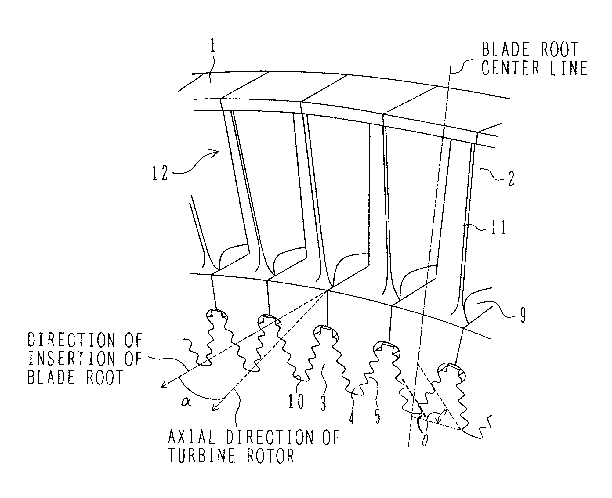
[0047]FIG. 1 is an oblique perspective view of steam turbine blades according to the present invention, the blades being attached to a turbine rotor. Each of the steam turbine blades in a first embodiment has an airfoil 2 and a fir-tree type blade root 4 which has an axis common to a blade groove (or a disc slot) 5 formed in an outer peripheral portion of a steam turbine rotor 3 and which is inserted in the blade groove 5 from one side in the axial direction of the turbine rotor for engagement between them. The blade root 4 is inserted in a direction forming a predetermined angle α larger than 0° relative to the axial direction of the turbine rotor. Hooks are formed in each of the fir-tree type blade root 4 and the blade groove 5 in plural stages in the radial direction of the turbine rotor. The steam turbine rotor 3 has a shaft and a wheel joined to the shaft. The wheel includes plural stages of slotted discs having slots into which the steam turbine blades are attached.
[0048]More ...
second embodiment
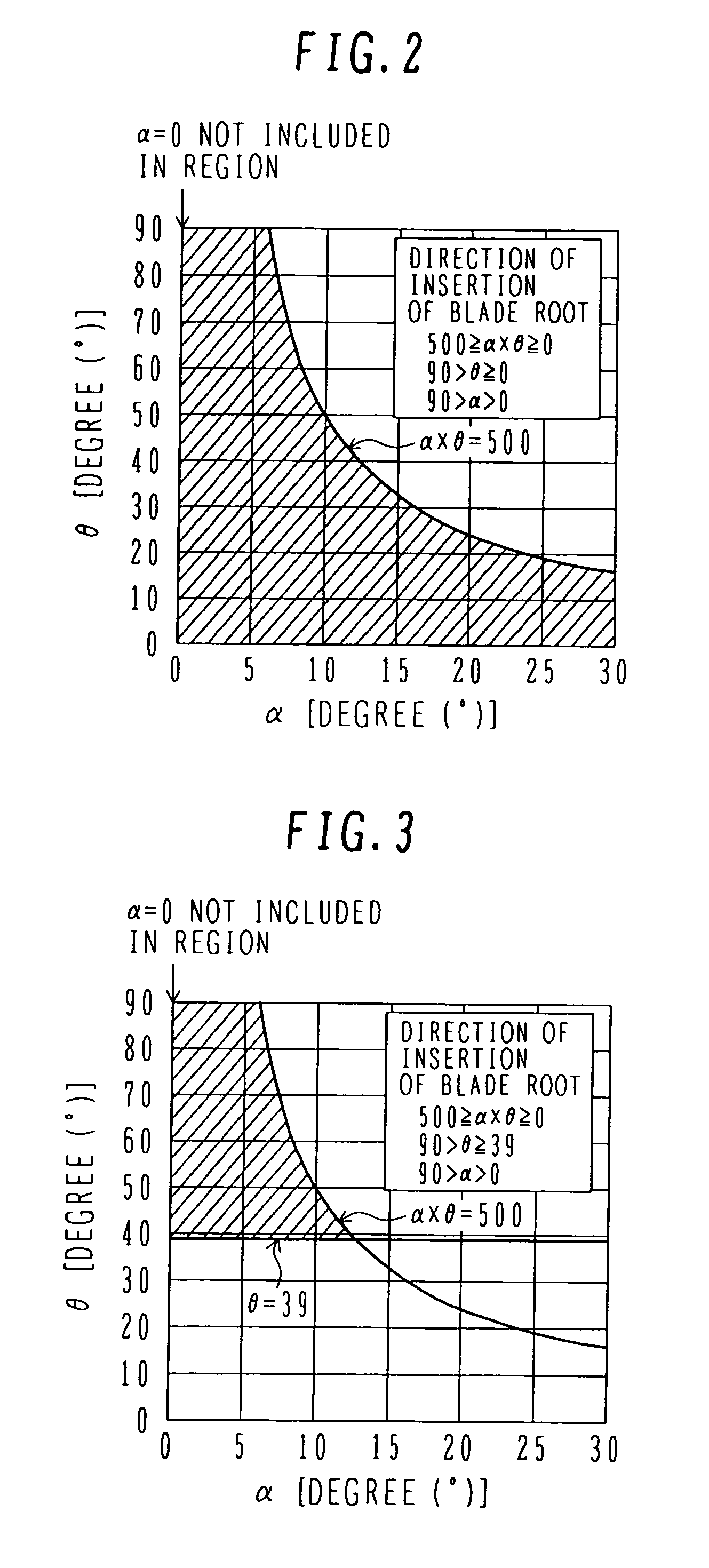
[0062]This second embodiment differs from the first embodiment in that a lower limit value for the range of the angle θ of the hook bearing surface is set to 39°, and the insert angle α of the blade root 4 and the angle θ of the hook bearing surface are satisfied by the following formulas 4, 5 and 6. The structure of the steam turbine blade in this second embodiment is the same as that in the first embodiment.
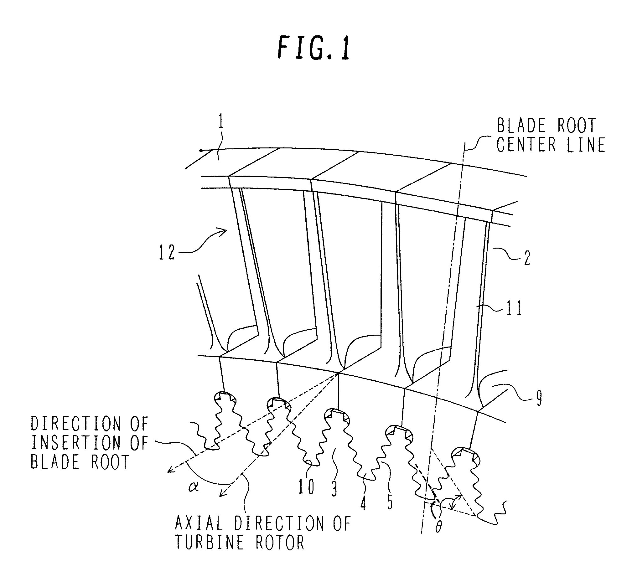
500≧α×θ≧0 (4)
90>θ≧39 (5)
90>α>0 (6)
[0063]FIG. 3 is a graph showing the relationship between the blade root insert angle α and the angle θ of the hook bearing surface. As shown in FIG. 3, the region specified by the formulas 4, 5 and 6 is a hatched region.
[0064]In this embodiment, by setting the angle θ of the hook bearing surface to be not smaller than 39°, even when any magnitude of centrifugal force acts on the turbine blade, the bearing surfaces of the hooks formed in the blade root 4 and the blade groove 5 cause relative slide between them such that the turbine blade slid...
third embodiment
[0067]In this embodiment, the range specified for the range of the angle θ of the hook bearing surface in any of the first and second embodiments is applied to only one among the plural stages of hooks 10, which is positioned at the innermost peripheral side in the radial direction of the turbine rotor 3. When the turbine root 4 of the axially-inserted inverted fir tree type is inserted in the direction forming the predetermined angle α relative to the axial direction of the turbine rotor 3, maximum peak stress is generated in many cases at the notch bottom under the hook 10 of the turbine groove 5, which is positioned at the innermost peripheral side in the radial direction of the turbine rotor 3. From such a practical point of view, the range specified for the value of the angle θ of the hook bearing surface is applied in this embodiment to only one among the plural stages of hooks 10, which is positioned at the innermost peripheral side in the radial direction of the turbine roto...
PUM
 Abstract
Description
Claims
Application Information
 - R&D
- Intellectual Property
- Life Sciences
- Materials
- Tech Scout
- Unparalleled Data Quality
- Higher Quality Content
- 60% Fewer Hallucinations
Browse by: Latest US Patents, China's latest patents, Technical Efficacy Thesaurus, Application Domain, Technology Topic, Popular Technical Reports.
© 2025 PatSnap. All rights reserved.Legal|Privacy policy|Modern Slavery Act Transparency Statement|Sitemap|About US| Contact US: help@patsnap.com


