
Display with a fluid balance structure

a technology of fluid balance and display, applied in the field of display, can solve the problems of affecting human health, bulky display of conventional cathode ray tube (crt), out of market, etc., and achieve the effect of saving effort, facilitating shaking of the supporting base, and effective preventing shaking

Inactive Publication Date: 2010-10-26
HANNSPREE INC
View PDF4 Cites 12 Cited by
  • Summary
  • Abstract
  • Description
  • Claims
  • Application Information

AI Technical Summary

Benefits of technology

"The present invention is a display with a fluid balance structure. It includes a screen, a supporting base, and a fluid. The supporting base connects with the screen and has an arc bottom with multiple hole-partition-plates. The fluid can flow through the hole-partition-plates and be distributed in different spaces. This allows users to easily adjust the angle of the display screen with one hand. The fluid can be liquid or solid particles, and the arc bottom can be made of soft material to prevent shaking. The hole-partition-plates are arranged parallel or unparallel to each other, and they have through holes that prevent fluid from flowing reversely. The hole-partition-plates can be engaged with and slide relative to each other to maintain stability. The first partition plate has a recess, and the second partition plate has a protrusion that engages with and slides in the recess. The invention provides a convenient and effort-saving way to adjust the angle of inclination of the display screen."

Problems solved by technology

Conventional Cathode Ray Tube (CRT) displays are bulky, and moreover, are detrimental to human health because of radiation.
Such setbacks have been seriously criticized and as such, CRT displays have been out of market gradually and replaced by flat panel displays, such as liquid crystal displays (LCDs).
Nevertheless, such a resilient pivoting or hinge structure for the LCD screen is not only complicate structure and difficult to be made, but also costs higher.
Further, in the case of violent shaking or vibrating, such resilient pivoting or hinge structure would not be stable enough and thus will cause unnecessary damages.
On the other hand, when the user needs to adjust the angle of inclination of the display screen, he / she needs to use one hand to hold the base of the display and the other hand to adjust the angle of inclination of the display screen, making the user feel inconvenient.
Moreover, the display screen using such a known pivoting structure always has a quite common appearance, and this dull configuration can hardly bring customers a deep impression, let alone encourage the customers to purchase the product.

Method used


Image

  • Display with a fluid balance structure
  • Display with a fluid balance structure
  • Display with a fluid balance structure

Examples


first embodiment

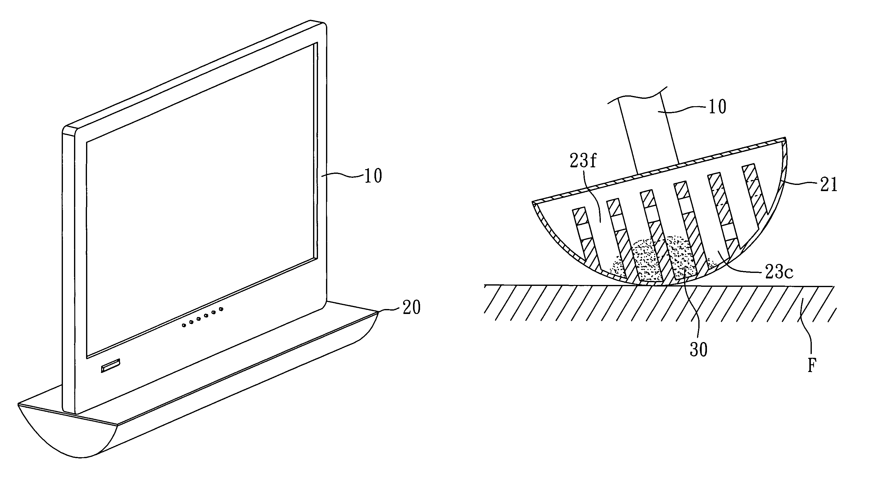
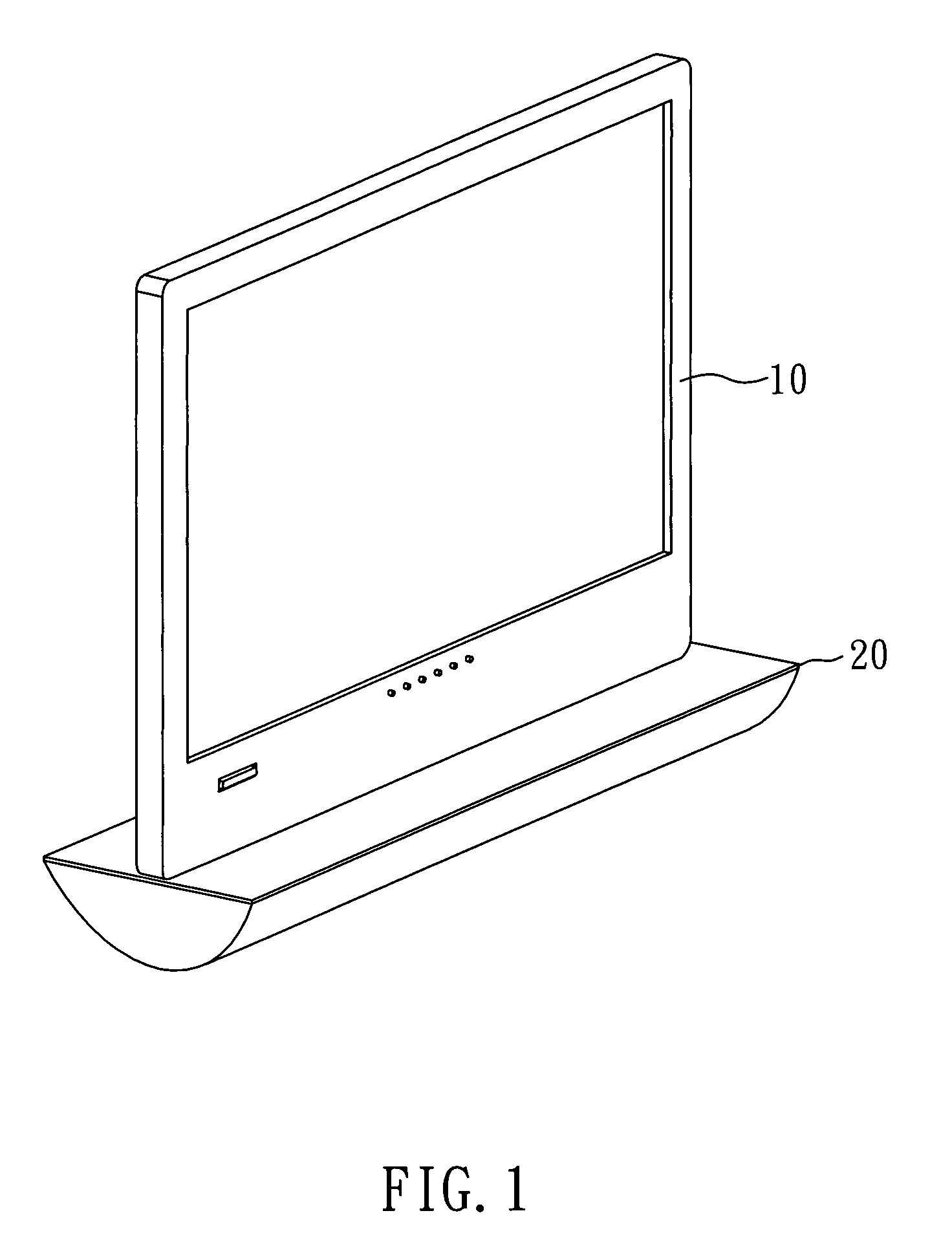
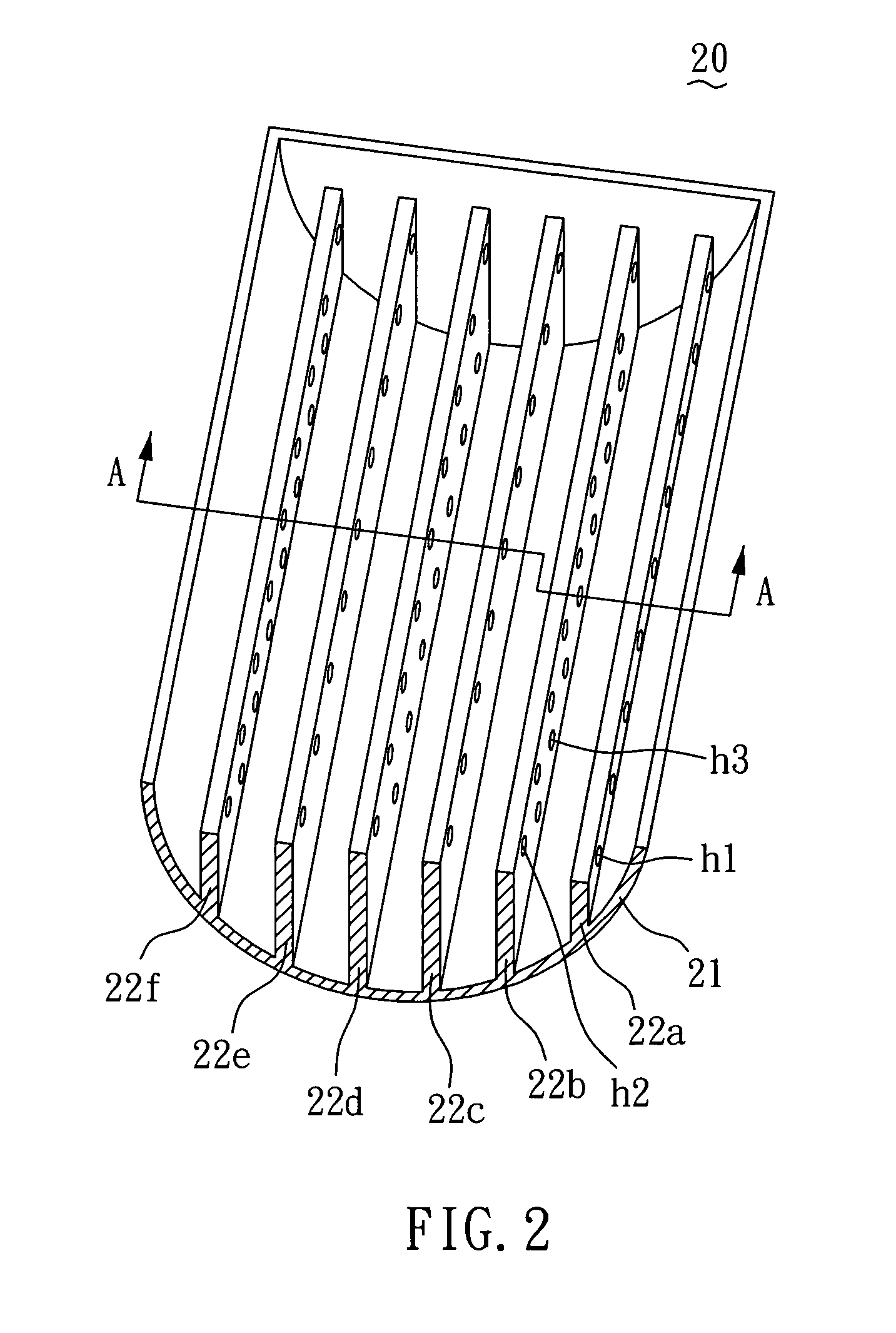
[0024]Referring to FIG. 1, a perspective view illustrating a display with a fluid balance structure according to the present invention, a display capable of adjusting angle of inclination with a fluid balance structure comprises a screen 10 for displaying information images and a supporting base 20 for connects with the screen 10. Referring to FIG. 2, a detailed internal view illustrating a supporting base of the display, the supporting base 20 includes an arc bottom 21 and a plurality of hole-partition-plates 22a to 22f provided inside an internal space S (shown in FIG. 3) of the supporting base 20 and extending upward from the arc bottom 21, where each of the hole-partition-plates 22a to 22f is provided, at its neighboring sides, with a receiving space, respectively. In the present embodiment, the supporting base 20 is made of rigid material.

[0025]Referring to FIG. 3, a cross-sectional view of the supporting base taken alone cutting line A-A of FIG. 2, all the hole-partition-plate...

second embodiment

[0030]Now referring to FIG. 5, a schematic view illustrating a supporting base 25 of the display according to the present invention, the feature of the present embodiment resides in that there are hole-partition-plates 24a to 24e arranged along an arc bottom 251 of the supporting base 25, where the hole-partition-plates 24a to 24e are arranged unparallel with one another, for instance, are isogonally arranged with one another according to the present embodiment.

third embodiment

[0031]Further, referring to FIG. 6, a partial perspective view illustrating a display according to the present invention, and to FIG. 7, a schematic view illustrating the first state of a hole-partition-plate, a supporting base 35 is made of a transparent material, and a button 36 extends outside of the supporting base 35. There are hole-partition-plates each including a first partition plate 33 and a second partition plate 34, where the first partition plate 33 is provided with a paired recesses 332 and the second partition plate 34 with a paired protrusions 342, such that the protrusions 342 can be engaged with and slide in the recesses 332. As a result, there are two kinds of states occurred for the hole-partition-plate, namely, through a relative slide action between the second partition plate 34 and the first partition plate 33, the positions of holes 341,331 thereon can or cannot be aligned with each other.

[0032]As shown in FIG. 7, the holes 341,331 of the second partition pla...


PUM


Abstract

A display with a fluid balance structure includes a screen, a supporting base, and a fluid. The supporting base connects with the screen, and includes an arc bottom provided with a plurality of hole-partition-plates, where each hole-partition-plate neighbors, at each side, a receiving space, respectively. The fluid can flow inside the supporting base and through the plural hole-partition-plates and be selectively distributed in various receiving spaces. Therefore, by changing the center of gravity for the display, a user can use one hand to adjust the angle of inclination for the screen. Further, the display is simple in structure and easy to manufacture.

Description

BACKGROUND OF THE INVENTION[0001]1. Field of the Invention[0002]The present invention relates to a display capable of adjusting angle of inclination, and more particularly, to a display capable of adjusting angle of inclination with a fluid balance structure.[0003]2. Description of Related Art[0004]Conventional Cathode Ray Tube (CRT) displays are bulky, and moreover, are detrimental to human health because of radiation. Such setbacks have been seriously criticized and as such, CRT displays have been out of market gradually and replaced by flat panel displays, such as liquid crystal displays (LCDs). With continuous improvement on the manufacturing technology of displays and the mass production of LCDs, nowadays LCD flat panel displays are quite popular, and have become the mainstream in the display market.[0005]LCDs achieve color rendering by controlling orientation of liquid crystal molecule arrangement so as to deflect light to reveal various colors. As such, a screen of the displa...

Claims


Application Information

Patent Timeline
Patent Type & Authority Patents(United States)
IPC IPC(8): A47B91/00
CPCF16M11/00F16M11/04F16M11/10F16M2200/041F16M2200/08Y10S248/91
Inventor TSAI, STEPHENLAI, LI-LI
Owner HANNSPREE INC
Learn More