Leak inspection method and leak inspector
a leak inspection and leak inspection technology, applied in the direction of instruments, fluid tightness measurement, heat measurement, etc., can solve the problems of gauge-pressure leak inspection time the leak inspection time of one device under inspection is as long as several tens of seconds, so as to achieve rapid leak inspection and precise drift correction coefficient
- Summary
- Abstract
- Description
- Claims
- Application Information
AI Technical Summary
Benefits of technology
Problems solved by technology
Method used
Image
Examples
first embodiment
[0099]FIG. 2 shows a leak inspector of an embodiment, operating with a drift correction coefficient calculated by the drift-correction-coefficient calculation method according to the present invention. In this embodiment, air pressure (gas pressure) is applied from a pneumatic source 11 to a device under inspection 20 and a reference tank 21, and it is determined whether the device 20 has a leak based on whether a pressure-difference detector 22 shows a pressure difference when a predetermined period of time elapses after the air pressure is applied.
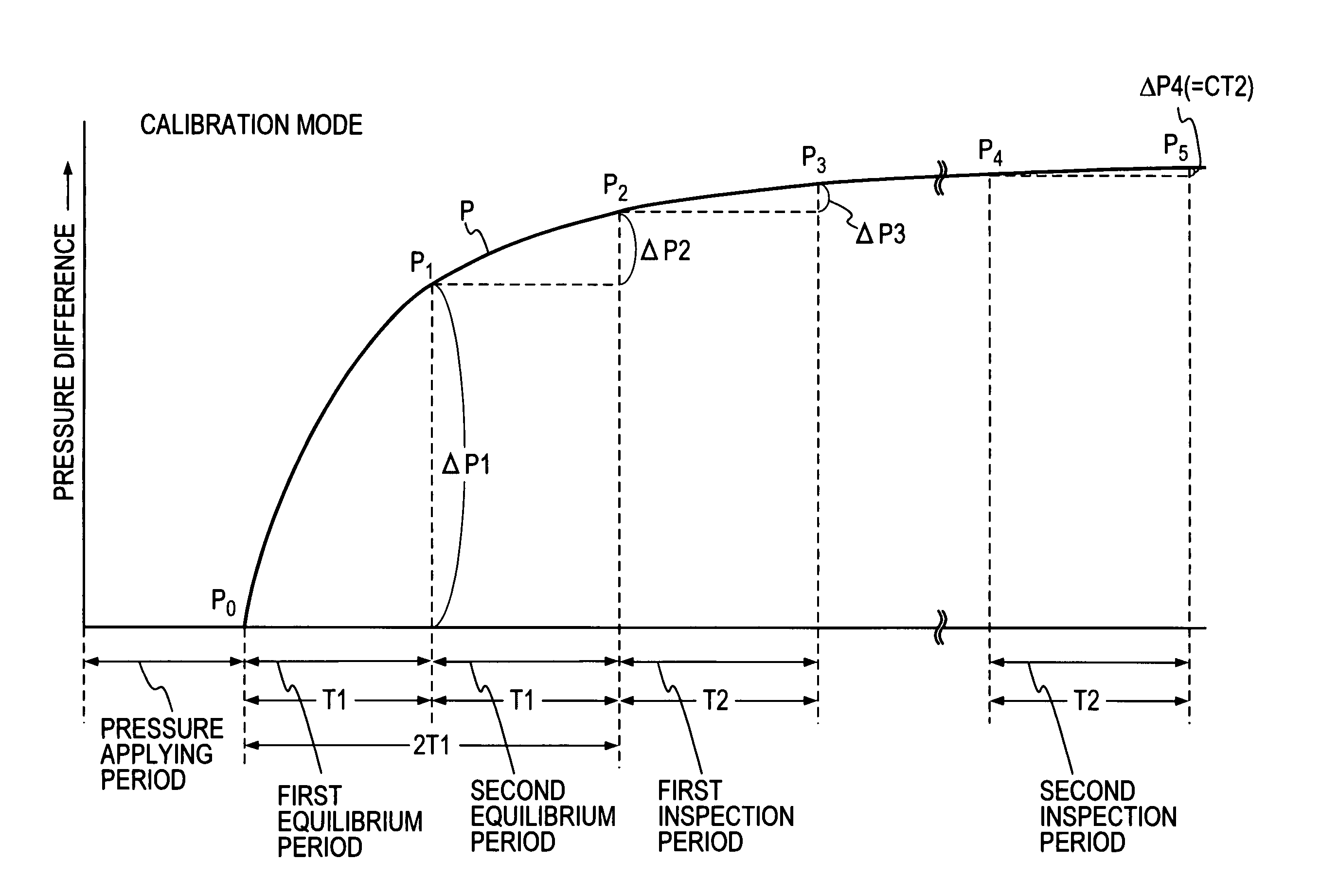
[0100]The leak inspector shown in FIG. 2 operates with a cycle formed of a pressure applying period, an equilibrium period, an inspection period, and a discharge period. In the present embodiment, a pressure-difference-change measurement section 40-1 is provided to measure pressure-difference changes ΔP1 and ΔP2 at the end of a first half of duration T1 and the end of a second half of duration T1 (hereinafter the first-half equilibrium p...
second embodiment
[0113]FIG. 5 shows a leak inspector for checking for a leak by using the drift calculation method, according to a second embodiment.
[0114]This embodiment differs from the embodiment shown in FIG. 2 in that temperature sensors 25 and 26 for measuring the ambient temperature θ and the temperature Θ of a device under inspection are further provided, and a calculation control unit 50 further includes a temperature-coefficient calculation section 53-8 and a temperature-coefficient storage section 53-9 for storing a temperature coefficient α calculated by the temperature-coefficient calculation section 53-8.
[0115]The temperature-coefficient calculation section 53-8 calculates the temperature-drift correction coefficient α using Expression (15) through measurements performed at different temperatures Θ1 and Θ2 of an identical device under inspection in a calibration mode. When the temperature-coefficient calculation section 53-8 calculates the temperature-drift correction coefficient α, th...
third embodiment
[0119]FIG. 6 shows a gauge-pressure type leak inspector according to a third embodiment of the present invention. This gauge-pressure type leak inspector differs from the pressure-difference leak inspector shown in FIG. 2 in that the gauge-pressure type leak inspector does not include the reference tank 21 and directly applies air pressure only to a device 20 under inspection to measure a change in pressure in the device 20. Therefore, in the third embodiment, the section formed of the automatic-zero-reset amplifier 41, the reset-signal generator 42, the sample and hold circuit 43, and the AD converter 44 is called a pressure-change measurement section 40-2.
[0120]Also for the gauge-pressure type leak inspector, in a calibration mode, an equilibrium period is divided into two parts, and pressure changes ΔQ1 and ΔQ2 are measured at the end of a first equilibrium period of duration T1 and the end of a second equilibrium period of duration T1. A pressure change ΔQ3 generated during a fi...
PUM
 Abstract
Description
Claims
Application Information
 - R&D
- Intellectual Property
- Life Sciences
- Materials
- Tech Scout
- Unparalleled Data Quality
- Higher Quality Content
- 60% Fewer Hallucinations
Browse by: Latest US Patents, China's latest patents, Technical Efficacy Thesaurus, Application Domain, Technology Topic, Popular Technical Reports.
© 2025 PatSnap. All rights reserved.Legal|Privacy policy|Modern Slavery Act Transparency Statement|Sitemap|About US| Contact US: help@patsnap.com


