
Microfluidic device for forming monodisperse lipoplexes

a monodisperse, lipoplex technology, applied in the field of microfluidic devices, can solve the problems of large size distribution of lipoplexes, irreproducible characteristics of lipoplexes, adversely affecting the overall efficiency of gene transfection,

Active Publication Date: 2010-10-12
RGT UNIV OF CALIFORNIA
View PDF3 Cites 1 Cited by
  • Summary
  • Abstract
  • Description
  • Claims
  • Application Information

AI Technical Summary

Benefits of technology

The invention relates to a method and device for generating monodisperse lipoplexes, which are important for delivering nucleic acids to cells. The method involves using a microfluidic device to create droplets of lipids and nucleic acids, which can then be used to transfer nucleic acids into cells. The device includes a main microfluidic channel, reactant inlet channels, and a droplet generation region where the lipids and nucleic acids are combined. The system also includes pumps to flow the lipids and nucleic acids into the reactant inlets and a mixing region to create the lipoplex droplets. The invention allows for the efficient and effective generation of monodisperse lipoplexes, which can be useful in research and medical applications.

Problems solved by technology

Unfortunately, these conventional techniques to generate lipoplexes have largely produced lipoplexes having characteristics that are irreproducible.
In addition, conventional preparation processes such as hand shaking and vortexing suffer from the problem that the resulting lipoplexes have a large size distribution.
Because the size of the individual lipoplex particles affects the rate of transfection, a population of lipoplexes having a broad array of sizes will adversely affect the overall efficiency of gene transfection.
The lack of control over the biophysical parameters that affect lipoplex generation is thus a barrier to consistently obtaining stable and monodisperse lipoplex formulations.

Method used


Image

  • Microfluidic device for forming monodisperse lipoplexes
  • Microfluidic device for forming monodisperse lipoplexes
  • Microfluidic device for forming monodisperse lipoplexes

Examples


Embodiment Construction

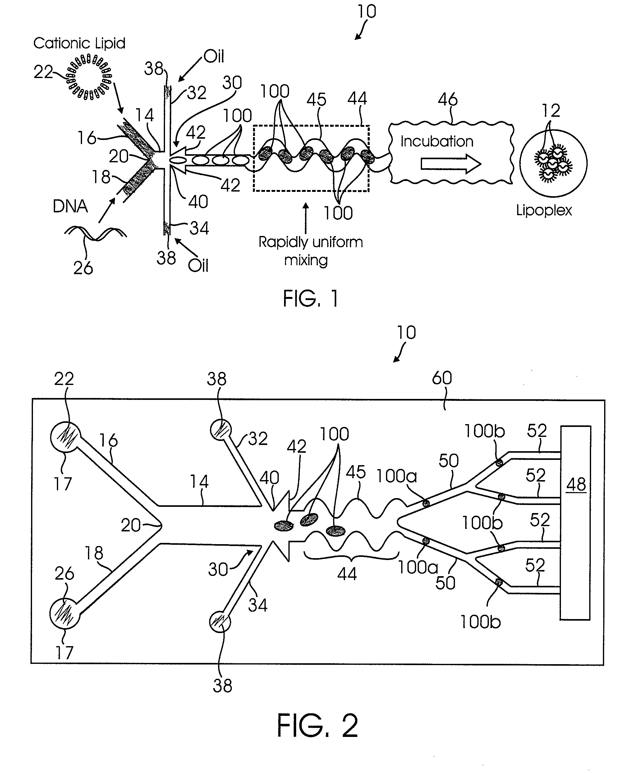
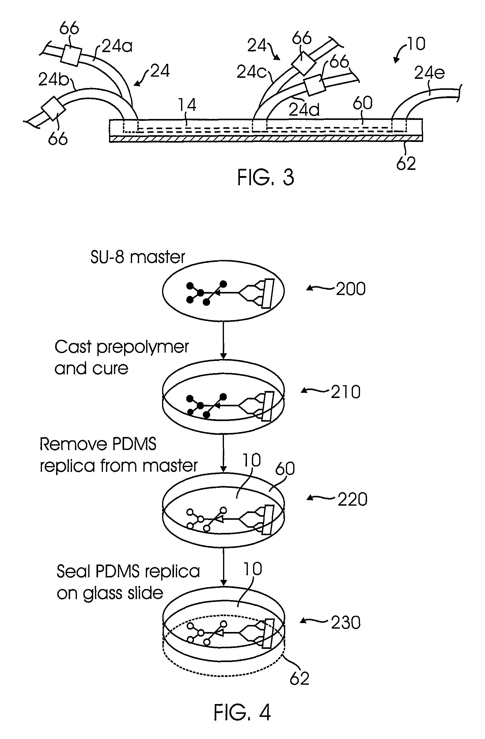
[0021]FIG. 1 illustrates a microfluidic device 10 for generating monodisperse lipoplex assemblies according to one embodiment. As used herein, the term “lipoplex assemblies” generally refers to the complex formed between a cationic lipid and nucleic acid after mixing and incubation. For example, the lipoplex assemblies may include one or more vesicles 12 that contain nucleic acid in an interior portion thereof. FIG. 1 illustrates a main microfluidic channel 14 that is connected to a first inlet channel 16 and a second inlet channel 18 via a junction 20. The first inlet channel 16 as illustrated in FIG. 1 is configured to receive a cationic lipid 22 (as illustrated in FIG. 2). The first inlet channel 16 may be coupled to a reservoir or chamber 17 that contains the cationic lipid 22. Alternatively, the first inlet channel 16 may be coupled via tubing 22 (as illustrated in FIG. 2 and which may be connected to the reservoir 17) or the like that is connected to a source of cationic lipid...


PUM

PropertyMeasurementUnit
volumesaaaaaaaaaa
sizeaaaaaaaaaa
widthaaaaaaaaaa

Abstract

A method for forming monodisperse lipoplex assemblies includes providing a microfluidic device having a main microfluidic channel coupled to first and second reactant inlet channels. The first inlet channel is used to deliver a cationic lipid to the main channel while the second channel is used to deliver a nucleic acid. A droplet generation zone is provided in the main channel at the intersection of first and second carrier channels that contain a hydrophobic fluid. The cationic lipid, nucleic acid, and the hydrophobic fluid are then pumped through the device. In the droplet generation zone, shear force from the hydrophobic fluid pinches off droplets. The cationic lipid and nucleic acid are mixed in the generated droplets as the droplets move within a mixing region. A plurality of splitting channels may be coupled to the outlet of the device to produce smaller, monodisperse droplets having picoliter volumes.

Description

RELATED APPLICATIONS[0001]This Application claims priority to U.S. Provisional Patent Application No. 60 / 746,840 filed on May 9, 2006. The above-noted Application is incorporated by reference as if set forth fully herein.FIELD OF THE INVENTION[0002]The field of the invention generally relates to microfluidic devices. More particularly, the field of the invention relates to microfluidic devices capable of generating a complex of nucleic acid (e.g., DNA) and a cationic lipid to form a non-viral liposomal carrier having a small size distribution. The device and method may be used as a pico-liter microreactor and microincubator for improving gene transfection and / or gene therapyBACKGROUND OF THE INVENTION[0003]There is a growing need to develop non-viral based carriers for the delivery of drugs, plasmic DNA, shRNA, and the like for pharmaceutical and therapeutic applications. Cationic lipid based liposomal carriers are an attractive non-viral delivery modality. Advantages of liposomal v...

Claims


Application Information

Patent Timeline
Patent Type & Authority Patents(United States)
IPC IPC(8): A61K9/127
CPCA61K9/1272A61K9/1277A61K31/70B01L3/0241B01L3/502784B01L2200/0673B01L2300/0681B01L2300/0816B01L2300/0864B01L2300/0867B01L2300/0883B01L2400/0421B01L2400/0424B01L2400/0436B01L2400/0478
Inventor LEE, ABRAHAM PHILLIPHSIEH, ALBERT TSUNG-HSI
Owner RGT UNIV OF CALIFORNIA
Learn More