
Dynamic spine stabilization device with travel-limiting functionality

a technology of spinal stabilization and functional limitation, which is applied in the field of spinal stabilization devices with travel-limiting functionality, can solve the problems of accelerating degeneration at those levels, reducing range of motion, and affecting the quality of life of patients, and achieves the effect of promoting reliable and effective spinal stabilization

Inactive Publication Date: 2010-10-12
RACHIOTEK
View PDF121 Cites 113 Cited by
  • Summary
  • Abstract
  • Description
  • Claims
  • Application Information

AI Technical Summary

Benefits of technology

[0014]According to still further exemplary embodiments of the present disclosure, the opposite termination of the travel-limiting structure may be affixed to the other / second structural member in a manner which prevents the elongate element from axial travel relative to the other / second structural member. In some such embodiments, the resilient element may be disposed against a first end of the other structural member, with the associated termination being disposed adjacent a second end of the other / second structural member opposite the first end thereof. The elongate element may extend through an aperture formed in the other / second structural member. In some such embodiments, a pocket is formed in the second end of the other structural member, and a lip is formed at the bottom of the pocket adjacent the aperture that extends therethrough. The associated termination may include a cylindrical collar lodged within the pocket no deeper than to a depth of the lip so as to axially align the other termination with such structural member. Moreover, the second structural member may additionally include a sleeve insert in the pocket into which the other termination is inserted, such sleeve functioning to enhance alignment and durability of the junction.
[0015]Also according to the present disclosure, an apparatus, device and / or system is provided in which the following elements / components are provided in combination: a first structural member, a second structural member, a wire coil spring disposed and mounted between respective first ends of the structural members, and a travel-limiting structure for limiting a distance by which the first and second structural elements may be separated. The travel-limiting structure typically includes an elongate element having first and second ends, a first termination at the first end of the elongate element, and a second termination at the second end of the elongate element. The assembly / subassembly associated with such combination advantageously functions to limit the relative travel of the first structural element and the second structural element.
[0017]The outer resilient member or spring of the stabilizing member is shielded from undue stress and / or undue extension by the limiting structure.
[0018]Depending on an overall length of the cable between the termination blocks, the stabilizing member can be employed to limit a linear and / or angular distance between the structural members / spring caps to any desired dimension.
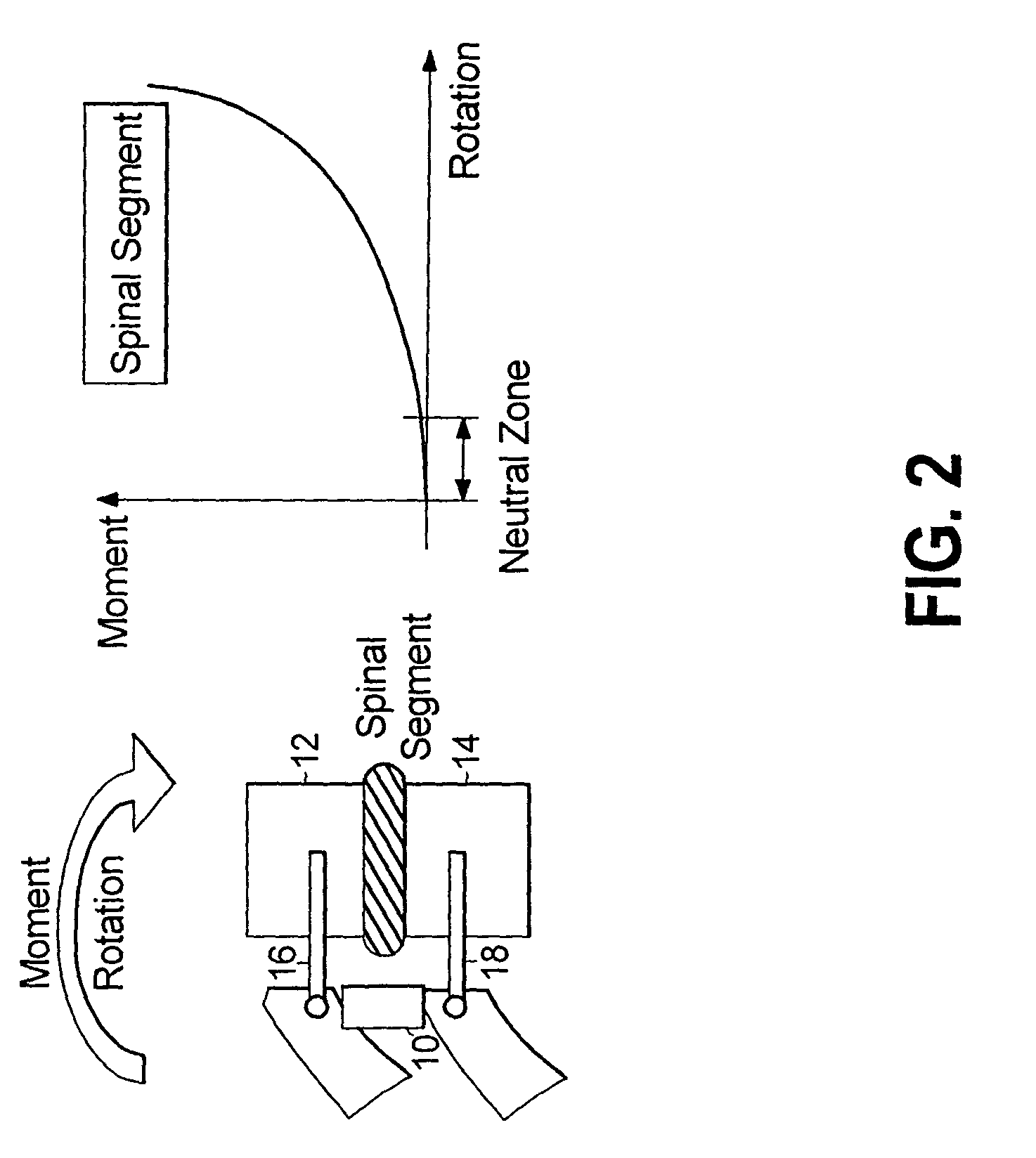
[0020]In another advantage stemming from such flexibility, the stabilization member can be tuned in relation to adjacent stabilization members and / or adjacent intervertebral segments in order to distribute the burden of spinal movement across multiple adjacent portions of the spine by inducing and / or forcing incrementally greater involvement of, or contributions from, adjacent intervertebral segments with respect to global spinal flexion, extension, or twist.
[0021]The stabilization member can be used to permit a small degree of intervertebral flexibility in the spine of a surgical patient whose condition might otherwise call for the employment of a spinal fusion technique.

Problems solved by technology

Low back pain is one of the most expensive diseases afflicting industrialized societies.
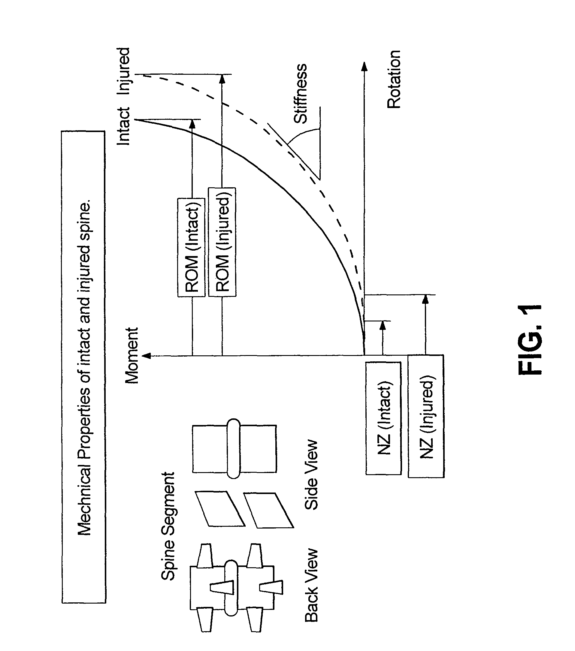
While fusion is effective about seventy percent of the time, there are consequences even to these successful procedures, including a reduced range of motion and an increased load transfer to adjacent levels of the spine, which may accelerate degeneration at those levels.
Further, a significant number of back-pain patients, estimated to exceed seven million in the U.S., simply endure chronic low-back pain, rather than risk procedures that may not be appropriate or effective in alleviating their symptoms.
While the flexibility afforded by such resilient elements is plainly critical to the effectiveness of the respective devices of which they form a part, the elevated force levels associated with the use of such resilient elements can result in such resilient elements developing significant levels of internal stress and / or responding to such stress by undergoing significant deformation, either or both of which may be undesirable depending on the particular device or surgical application.

Method used


Image

  • Dynamic spine stabilization device with travel-limiting functionality
  • Dynamic spine stabilization device with travel-limiting functionality
  • Dynamic spine stabilization device with travel-limiting functionality

Examples


Embodiment Construction

[0062]The present disclosure provides advantageous devices, systems and methods for spinal stabilization and / or alternative surgical implant applications. More particularly, the present disclosure provides devices, systems and methods that deliver dynamic stabilization to the spine so as to provide clinically efficacious results. The exemplary embodiments disclosed herein are illustrative of the advantageous spine stabilization systems and surgical implants of the present disclosure, and methods / techniques for implementation thereof. It should be understood, however, that the disclosed embodiments are merely exemplary of the present invention, which may be embodied in various forms. Therefore, the details disclosed herein with reference to exemplary dynamic spinal stabilization systems and associated methods / techniques are not to be interpreted as limiting, but merely as the basis for teaching one skilled in the art how to make and / or use the advantageous dynamic spinal stabilizatio...


PUM


Abstract

Spinal stabilization devices, systems and methods are provided that include a stabilization member including a first structural member that mounts to a pedicle screw, a second structural member adjacent the first structural member and that can move away therefrom, a resilient element mounted between the structural members and that elongates to accommodate relative movement therebetween, and a travel-limiting structure mounted between the structural members and that defines and imposes upon the stabilization member a maximum distance by which the first and second structural members may be separated. The travel-limiting structure can include an axially inextensible, laterally flexible elongate element, e.g., wire-rope cable, disposed between the structural members. The resilient element extends between respective first ends of the structural members, while the travel-limiting structure can include terminations at opposite ends of the elongate element and mounted to respective second ends of the structural members opposite the first ends thereof.

Description

BACKGROUND OF THE INVENTION[0001]1. Technical Field[0002]The present disclosure relates to advantageous methods and apparatus for spinal stabilization. More particularly, the present disclosure relates to methods and apparatus for providing dynamic stabilization to the spine so as to provide clinically efficacious results and to such methods / apparatus that include travel-limiting functionality.[0003]2. Background Art[0004]Low back pain is one of the most expensive diseases afflicting industrialized societies. With the exception of the common cold, it accounts for more doctor visits than any other ailment. The spectrum of low back pain is wide, ranging from periods of intense disabling pain which resolve to varying degrees of chronic pain. The conservative treatments available for lower back pain include: cold packs, physical therapy, narcotics, steroids and chiropractic maneuvers. Once a patient has exhausted all conservative therapy, the surgical options generally range from micro ...

Claims


Application Information

Patent Timeline
Patent Type & Authority Patents(United States)
IPC IPC(8): A61B17/70
CPCA61B17/7007A61B17/7025A61B17/7028A61B17/7035A61B17/7004A61B17/7031A61B17/7041
Inventor TIMM, JENS P.HILDEBRAND, BRYAN
Owner RACHIOTEK
Learn More