Test device for electronic product

a technology for testing devices and electronic products, applied in the direction of mechanical measuring arrangements, instruments, and mechanical means, can solve the problems of difficult to achieve the transformation of horizontal pushing force 1, marked reduction in the precision of the tester, and low precision

Inactive Publication Date: 2010-10-12
INVENTEC APPLIANCES CORP
View PDF3 Cites 0 Cited by
  • Summary
  • Abstract
  • Description
  • Claims
  • Application Information

AI Technical Summary

Benefits of technology

[0012]In view of the above-mentioned circumstances, an objective of the present invention is to provide a test device for an electronic product to solve the problems of high cost and insufficient precision occurred in a reliability test.

Problems solved by technology

A. the turbine shaft 111 has low precision due to the limitation of the anti-friction design and the mechanical lever self-design (about 0.5 mm of die tolerance), so the transformation of horizontal pushing force is difficult to achieve 1 mm
After a period of use, the turbine shaft wears out significantly will directly lead to a marked reduction in the precision of the tester as well as it is hard to improve through calibration.
Besides, there are high-precision insertion testers in prior art, but there are still some drawbacks as follows:
Such tester is precise but expensive, with a finite life, so the cost per testing is very high; and

Method used


Image

  • Test device for electronic product
  • Test device for electronic product
  • Test device for electronic product

Examples


Embodiment Construction

[0017]Exemplary embodiments of the present invention are described herein in the context of a test device for an electronic product.

[0018]Those of ordinary skill in the art will realize that the following detailed description of the exemplary embodiment(s) is illustrative only and is not intended to be in any way limiting. Other embodiments will readily suggest themselves to such skilled persons having the benefit of this disclosure. Reference will now be made in detail to implementations of the exemplary embodiment(s) as illustrated in the accompanying drawings. The same reference indicators will be used throughout the drawings and the following detailed description to refer to the same or like parts.

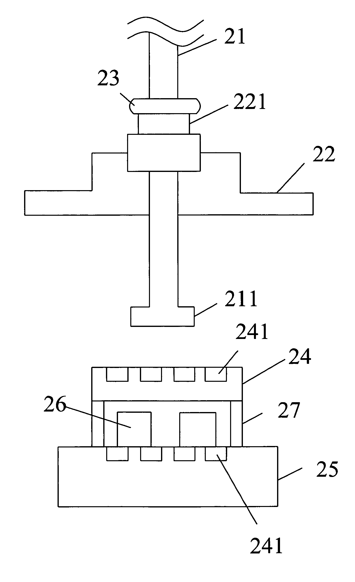
[0019]FIG. 2 illustrates a schematic view showing a test device for an electronic product according to an embodiment of the present invention. The test device in the drawing is used to test the reliability of an electronic product, and comprises a vertical pressing pole 21, a movable p...


PUM

PropertyMeasurementUnit
weightaaaaaaaaaa
pressureaaaaaaaaaa
heightaaaaaaaaaa

Abstract

A test device for an electronic product includes a vertical pressing pole having a pushing end. The test device also includes a movable platform with a sticking point, wherein upward movement of the movable platform moves the vertical pressing pole upwards by the sticking point. The vertical pressing pole passes through a balance weight which rests on the sticking point. A pressurized platform bears pressure from the pushing end, when the pushing end is pushed onto the pressurized platform. A load-bearing platform supports the pressurized platform and the electronic product located below the pressurized platform. The product is pressed between the pressurized platform and the load-bearing platform due to the pressure from the pushing end lying on the pressurized platform. When the movable platform is further moved downwards after the pushing end is on the pressurized platform, the sticking point bearing the balance weight is separate from the movable platform.

Description

BACKGROUND OF THE INVENTION[0001](a) Field of the Invention[0002]The present invention relates to a test device, and more particularly to a test device capable of performing high-precision testing for an electronic product by the interlocking action of a force controllable vertical pressing pole, a pressure platform and a limiting position slice.[0003](b) Description of the Prior Art[0004]Presently, as the electronic product technology is becoming more and more mature, the structures of electronic products have higher and higher precision. Great importance is attached to the reliability tests of electronic products, among which a pressing test and a pulling / pushing test are the two most important items.[0005]In the prior art, the test apparatus with lower precision shown in FIG. 1 is mostly used in the reliability tests. Such apparatus employs active and integrated transmission, and it transforms power from a motor into a push-pull force in the horizontal direction through a turbine...

Claims


Application Information

Patent Timeline
Patent Type & Authority Patents(United States)
IPC IPC(8): G01N3/08
CPCG01N3/08G01N2203/0441
Inventor WANG, J. J.SUN, LI-MIN
Owner INVENTEC APPLIANCES CORP
Why Eureka
Try Eureka