
Apparatus and method for simulating a wave field synthesis system

a wave field synthesis and apparatus technology, applied in the field of wave field synthesis technique, can solve the problems of affecting the quality of spatial sound reproduction of natural, but also virtual environments, and wave field synthesis has only rarely been used in the field of wave field synthesis

Active Publication Date: 2010-10-05
FRAUNHOFER GESELLSCHAFT ZUR FOERDERUNG DER ANGEWANDTEN FORSCHUNG EV
View PDF22 Cites 15 Cited by
  • Summary
  • Abstract
  • Description
  • Claims
  • Application Information

AI Technical Summary

Benefits of technology

This solution allows for real-time simulation and verification of audio scene descriptions, ensuring compatibility and quality across different wave field synthesis systems, reducing the need for intensive manual testing and accommodating various system capacities, while maintaining artistic freedom for sound designers.

Problems solved by technology

In previous audio systems, a substantial disadvantage lies in the quality of the spatial sound reproduction of natural, but also of virtual environments.
All usual techniques have the disadvantage that both the site of the loudspeakers and the position of the listener are already impressed on the transmission format.
With wrong arrangement of the loudspeakers with reference to the listener, the audio quality suffers significantly.
Due to this method's enormous demands on computer power and transfer rates, the wave field synthesis has up to now only rarely been employed in practice.
Although the wave field synthesis functions well for environments the properties of which are known, irregularities occur if the property changes or the wave field synthesis is executed on the basis of an environment property not matching the actual property of the environment.
It is assumed that a loudspeaker sends out a sound signal against a wall, the reflection of which is undesired.
But it still suffers from the problem that the central wave field synthesis module, which performs the actual main rendering, i.e. which calculates the individual synthesis signals for the loudspeakers depending on the positions of the virtual sources and depending on the loudspeaker positions, represents a “bottleneck” for the entire system.
If the central rendering unit thus is capable of rendering 32 virtual sources at the same time, for example, i.e. to calculate the synthesis signals for these 32 virtual sources at the same time, serious capacity bottlenecks occur, if more than 32 sources are active at one time in one audio scene.
It is disadvantageous in the concept described that it is relatively rigid particularly in the creation of the audio scene descriptions.
It is disadvantageous in this concept that the sound master creating the audio scene description has to concentrate on boundary conditions of the wave field synthesis system, which actually do not concern the creative side of the audio scene.
It is further disadvantageous in the described concept that, when an audio scene description from a wave field synthesis system with a certain first behavior, for which the audio scene description has been designed, is supposed to run on another wave field synthesis system with a second behavior, for which the audio scene has not been designed.
If one would only have the audio scene description run on the system for which it has not been designed, problems would occur in that audible errors will be introduced if the second system is less powerful than the first system.
Particularly the problem of the concurrent or almost concurrent perception of two virtual sources, which should be synchronous, is very problematic, especially since only manual test listening action and a subjective assessment of the quality at certain places in the reproduction room previously has been possible for this purpose.

Method used


Image

  • Apparatus and method for simulating a wave field synthesis system
  • Apparatus and method for simulating a wave field synthesis system
  • Apparatus and method for simulating a wave field synthesis system

Examples


Embodiment Construction

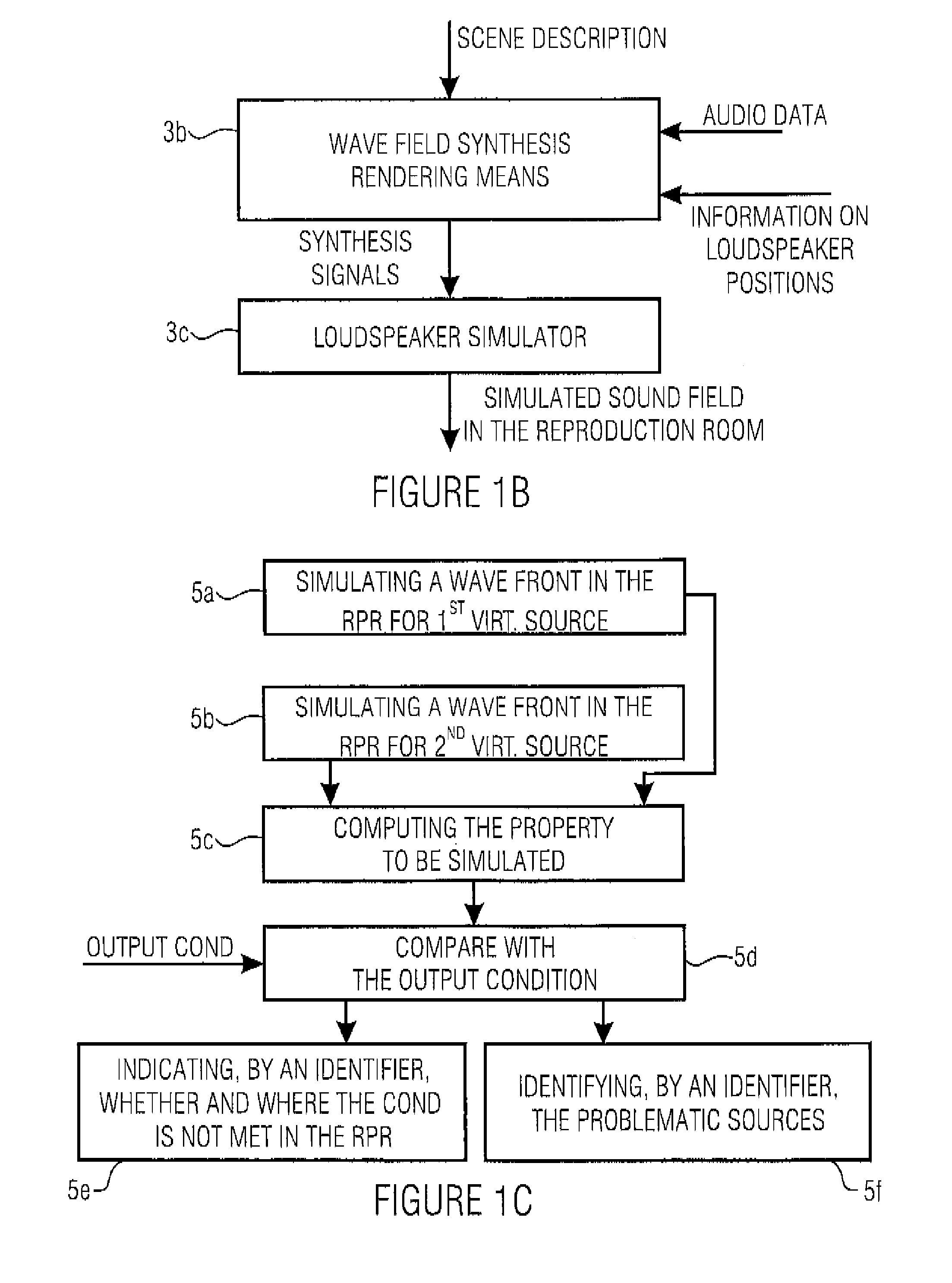
[0065]FIG. 1A shows a schematic illustration of an inventive apparatus for simulating a wave field synthesis system with a reproduction room in which one or more loudspeaker arrays and a wave field synthesis rendering means coupled to the loudspeaker array can be attached. The inventive apparatus includes a means 1 for providing an audio scene description defining a temporal sequence of audio objects, wherein an audio object comprises an audio file for a virtual source or a reference to the audio file and information on a source position of the virtual source. The audio files may either be directly contained in the audio scene description 1 or may be identifiable by references to audio files in an audio file database 2 and be supplied to a means 3 for simulating the behavior of the wave field synthesis system.

[0066]Depending on the implementation, the audio files are controlled via a control line 1a or supplied to the simulation means 2 via a line 1b, in which also the source positi...


PUM


Abstract

For simulating a wave field synthesis system, an audio scene description defining a temporal sequence of audio objects is provided, an audio object having an audio file for a virtual source or a reference to the audio file and information on a source position of the virtual source. Furthermore, an output condition the wave field synthesis system is to satisfy is given. Furthermore, a simulator for simulating the behavior of the wave field synthesis system for the audio scene description, using the audio data and the source positions as well as information on the wave field synthesis system, is provided. Finally a checker performs a check to determine if the simulated behavior of the wave field synthesis system satisfies the output condition. This achieves more flexible audio scene description creation as well as flexible portability of an audio scene description developed for one system to another wave field synthesis system.

Description

CROSS-REFERENCE TO RELATED APPLICATIONS[0001]This application is a continuation of copending International Application No. PCT / EP2006 / 001413, filed Feb. 16, 2006, which designated the United States and was not published in English.BACKGROUND OF THE INVENTION[0002]1. Field of the Invention[0003]The present invention relates to the wave field synthesis technique, and particularly to tools for creating audio scene descriptions and / or for verifying audio scene descriptions.[0004]2. Description of the Related Art[0005]There is an increasing need for new technologies and innovative products in the area of entertainment electronics. It is an important prerequisite for the success of new multimedia systems to offer optimal functionalities or capabilities. This is achieved by the employment of digital technologies and, in particular, computer technology. Examples for this are the applications offering an enhanced close-to-reality audiovisual impression. In previous audio systems, a substanti...

Claims


Application Information

Patent Timeline
Patent Type & Authority Patents(United States)
IPC IPC(8): G06F17/00H04R25/00H04R29/00
CPCH04S3/008H04S2420/13
Inventor REICHELT, KATRINGATZSCHE, GABRIELMELCHIOR, FRANKBRIX, SANDRA
Owner FRAUNHOFER GESELLSCHAFT ZUR FOERDERUNG DER ANGEWANDTEN FORSCHUNG EV
Learn More