
Test method and apparatus for spark plug insulator

a technology of spark plugs and test methods, which is applied in the direction of spark plugs, instruments, machines/engines, etc., can solve the problems of increased equipment cost, deterioration of productivity, and labor-intensive pressure control operation, so as to improve accuracy, improve productivity, and improve cost

Active Publication Date: 2010-10-05
NGK SPARK PLUG CO LTD
View PDF16 Cites 7 Cited by
  • Summary
  • Abstract
  • Description
  • Claims
  • Application Information

AI Technical Summary

Benefits of technology

The present invention provides a method and apparatus for testing the presence or absence of defects in a cylindrical spark plug insulator without the need for expensive and time-consuming equipment. The method involves using a first test electrode and a second test electrode to create a high-pressure condition for the defect detection test and then recovering the normal-pressure conditions for replacement of the insulator after the test. The apparatus includes a power source, a control unit, and an ammeter for measuring the electric current between the test electrodes. The technical effects of the invention include improved accuracy and efficiency in defect detection without cost increase and productivity deterioration.

Problems solved by technology

However, the proposed high-pressure test method requires additional major equipment such as high-pressure air supply device and pressure-resistant container and time- and labor-consuming pressure control operation to create the high-pressure conditions for the defect detection test and to recover the normal-pressure conditions for removal / replacement of the insulator after the defect detection test.
This causes increase in equipment cost and deterioration in productivity.

Method used


Image

  • Test method and apparatus for spark plug insulator
  • Test method and apparatus for spark plug insulator
  • Test method and apparatus for spark plug insulator

Examples


first embodiment

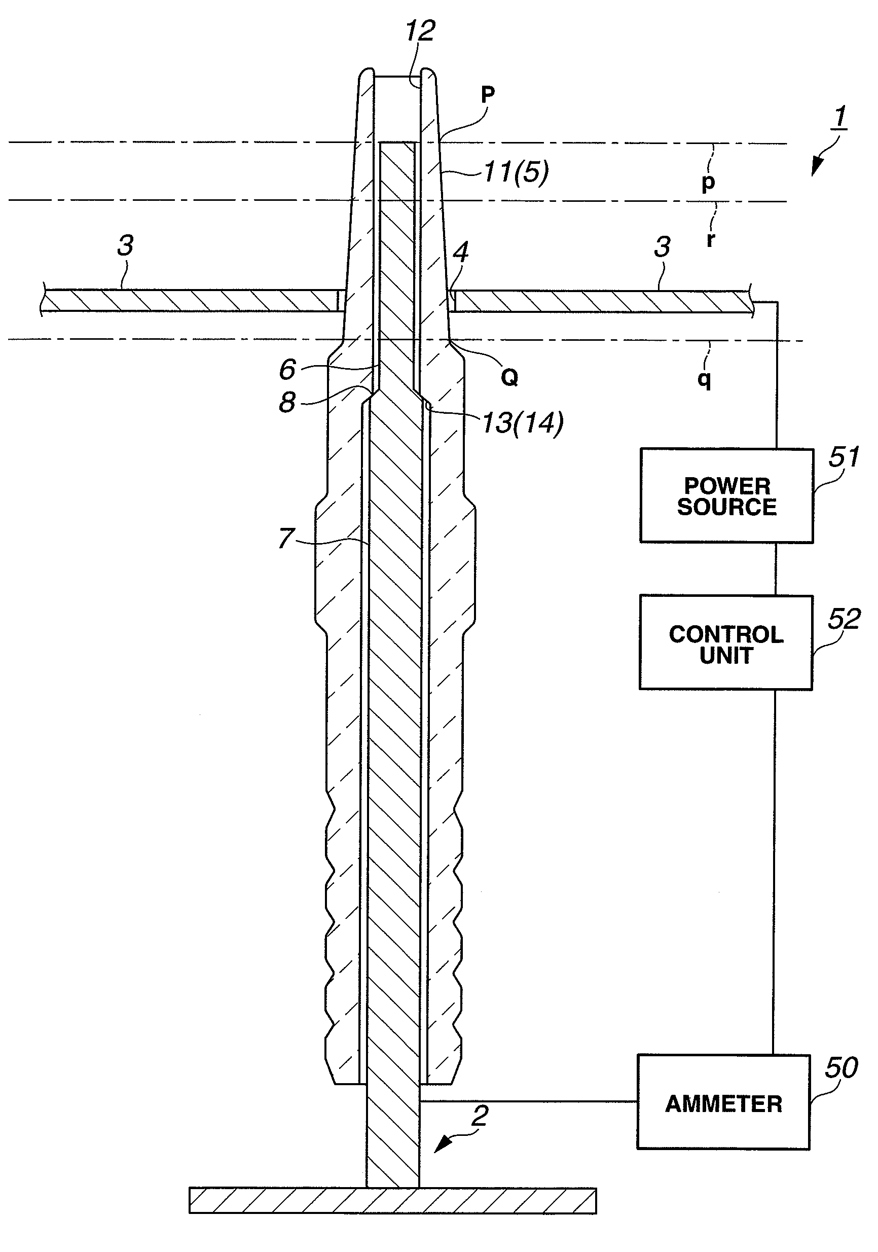
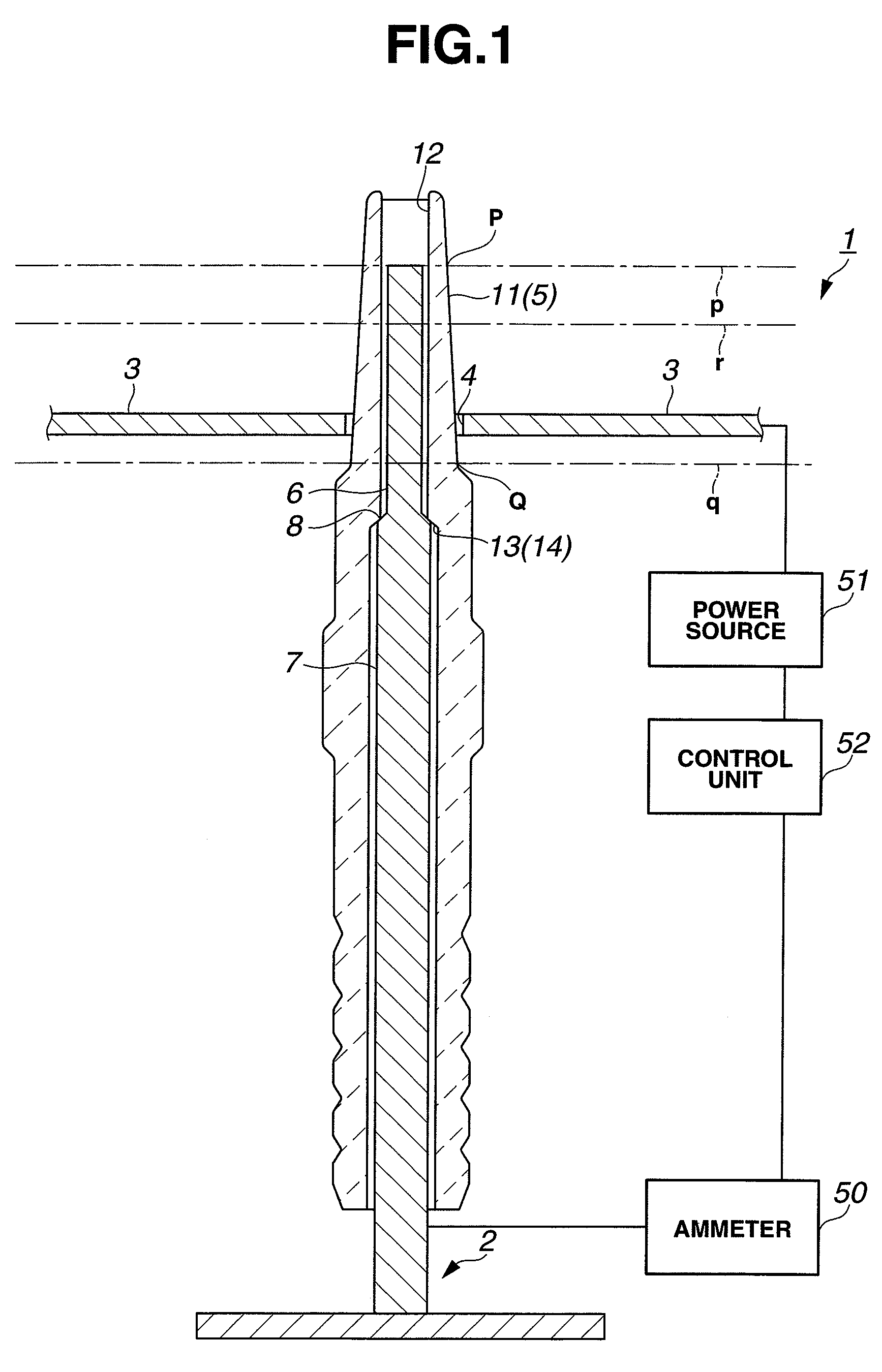
[0024]The first embodiment refers to a method for testing the presence or absence of a defect in a ceramic insulator 11 by a test apparatus 1. The ceramic insulator 11 is designed, for use in a spark plug, as a cylindrical molded sintered piece of a ceramic material e.g. alumina with an axial through hole 12 as shown in FIG. 1. A stepped surface 13 is formed on the axial through hole 12 of the ceramic insulator 11 so as to retain thereon a center electrode of the spark plug. In the first embodiment, the ceramic insulator 11 has a shape that varies in thickness in the axial direction thereof and defines a contour part of the spark plug. (Hereinafter, the ceramic insulator 11 as the test sample may occasionally be referred to as the sample insulator.)

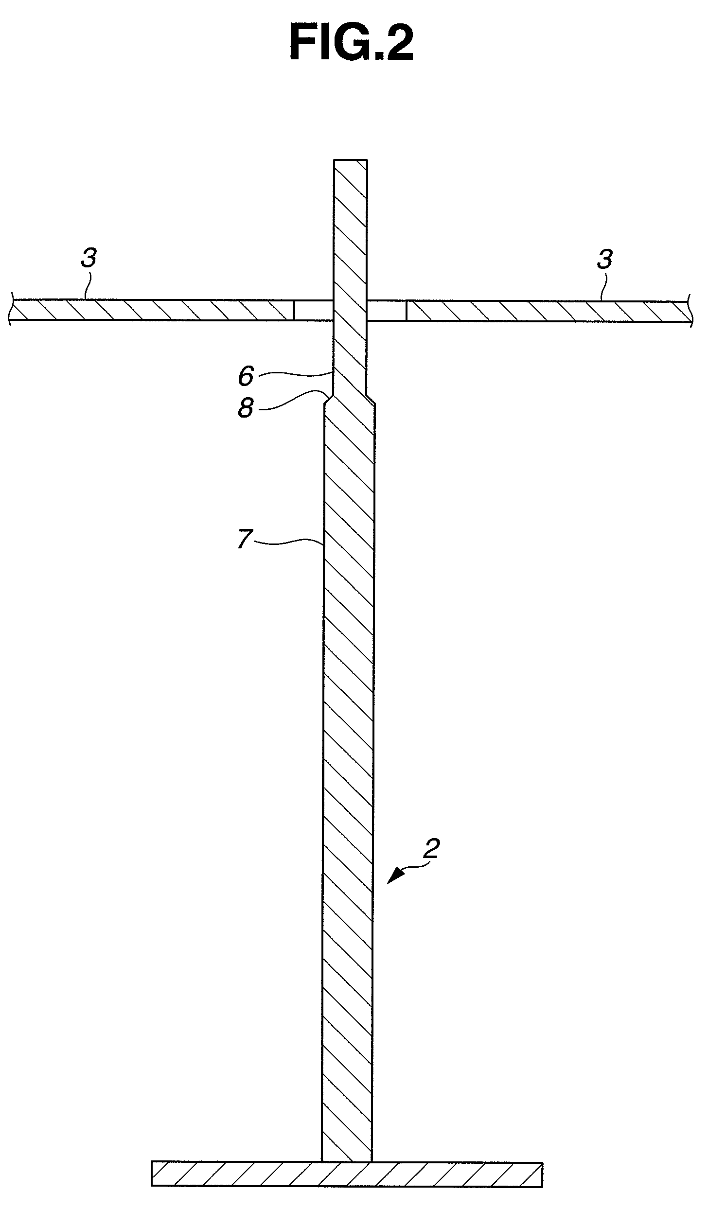
[0025]As shown in FIGS. 1 and 2, the test apparatus 1 includes a first test electrode 2, a second test electrode 3, a reference insulator 5, an ammeter 50, a direct-current power source 51 and a control unit 52.

[0026]The first test electr...

second embodiment

[0050]The second embodiment is similar to the first embodiment, except that a test apparatus 101 of the second embodiment is capable of simultaneous defect detection tests on a plurality of ceramic insulators 11 at a plurality of points. For simplification purposes, one ceramic insulator 11 is illustrated in FIGS. 5 and 6. Although the test apparatus 101 has an ammeter 50, a direct-current power source 51 and a control unit 52 as in the case of the first embodiment, these structural components 50, 51 and 52 are omitted from FIGS. 5 and 6 for simplification purposes.

[0051]As shown in FIG. 5, the test apparatus 101 includes a net-shaped holder 15 with openings 15a so that the ceramic insulators 11 can be held in the respective openings 15a of the holder 15 and carried at once by movement of the holder 15. The holder 15 is supported by an insulating support member and kept from electrical contact with the ceramic insulators 11 so as not to produce an electrical effect on the ceramic in...

third embodiment

[0064]The third embodiment is similar to the second embodiment, except that a test apparatus 201 of the third embodiment has a different number of second test electrodes and carries out a test voltage determination process in a different manner. In FIG. 8, one ceramic insulator 11 is illustrated for simplification purposes. Although the test apparatus 201 has an ammeter 50, a direct-current power source 51 and a control unit 52 as in the case of the first and second embodiments, these structural components 50, 51 and 52 are omitted from FIG. 8 for simplification purposes.

[0065]As shown in FIG. 8, the test apparatus 201 has three second test electrodes 3a, 3b and 3c: two second test electrodes 3a and 3b on the front side of the holder 15 and one second test electrode 3c on the rear side of the holder 15.

[0066]In the third embodiment, the defect detection test program takes place in the same manner as in the first and second embodiments, except for the test voltage determination proce...


PUM

PropertyMeasurementUnit
distancesaaaaaaaaaa
short-circuit voltageaaaaaaaaaa

Abstract

There is provided a test method for detecting the presence or absence of a defect in a spark plug insulator, including a reference voltage determination process, a test area determination process, a test voltage determination process and a current detection process. In the reference voltage determination process, a reference voltage VF is determined. In the test area and voltage determined processes, test area and voltage are determined so as not to incur a flashover on the basis of a reference insulator of the same material, shape and size as the spark plug insulator when the reference insulator is placed in position between first and second test electrodes. In the current detection step, the test voltage is applied between the first and second test electrodes to detect an electric current between the first and second test electrodes.

Description

BACKGROUND OF THE INVENTION[0001]The present invention relates to a method and apparatus for testing the presence or absence of a defect in a spark plug insulator.[0002]Hereinafter, the term “front” refers to a discharge side with respect to the axial (longitudinal) direction of an insulator when assembled into a spark plug and the term “rear” refers to a side opposite to the front side.[0003]A spark plug includes an insulator, a center electrode disposed in an axial through hole of the insulator, a metal shell disposed around an outer periphery of the insulator and a ground electrode attached to a front end of the metal shell to define a discharge gap between the center electrode and the ground electrode. By the application of a high voltage to the center electrode, a spark discharge occurs within the discharge gap between the center electrode and the ground electrode. In the presence of a defect e.g. a pin hole in the insulator, however, there is a possibility the spark discharge ...

Claims


Application Information

Patent Timeline
Patent Type & Authority Patents(United States)
IPC IPC(8): G01N27/00H01T13/58H01T13/60
CPCH01T13/60
Inventor HONDA, TOSHITAKAKURONO, HIROKAZUKATO, TOMOAKI
Owner NGK SPARK PLUG CO LTD
Learn More