Energy signal processing system

a technology of energy signal and processing system, applied in the direction of solar heat devices, instruments, electric discharge lamps, etc., can solve the problems of occlusion of transmission and/or reading path, complex and space-consuming of both motor assemblies, and high cost of assembly

Active Publication Date: 2010-09-28
OCULAR ROBOTICS
View PDF27 Cites 18 Cited by
  • Summary
  • Abstract
  • Description
  • Claims
  • Application Information

AI Technical Summary

Benefits of technology

[0013]means for rotating said energy signal processing element about said processing element axis such that at least one of the following is effected:

Problems solved by technology

A disadvantage of this device is its complexity and the amount of space required to package both motor assemblies.
A disadvantage of this arrangement is that the mechanism to rotate the mirror is required to be at opposite ends to the emitting / receiving unit.
As a result, either the emitting / receiving unit or mirror rotation mechanism is exposed above the main support housing making it vulnerable to damage.
Furthermore, having either the emitting / receiving unit or mirror rotation mechanism suspended above the other, necessitates additional support structures, which may create occlusions in the transmission and / or reading path.
Disadvantageously, since the static array is not moveable, its sensing range is fixed.

Method used


Image

  • Energy signal processing system
  • Energy signal processing system
  • Energy signal processing system

Examples


Embodiment Construction

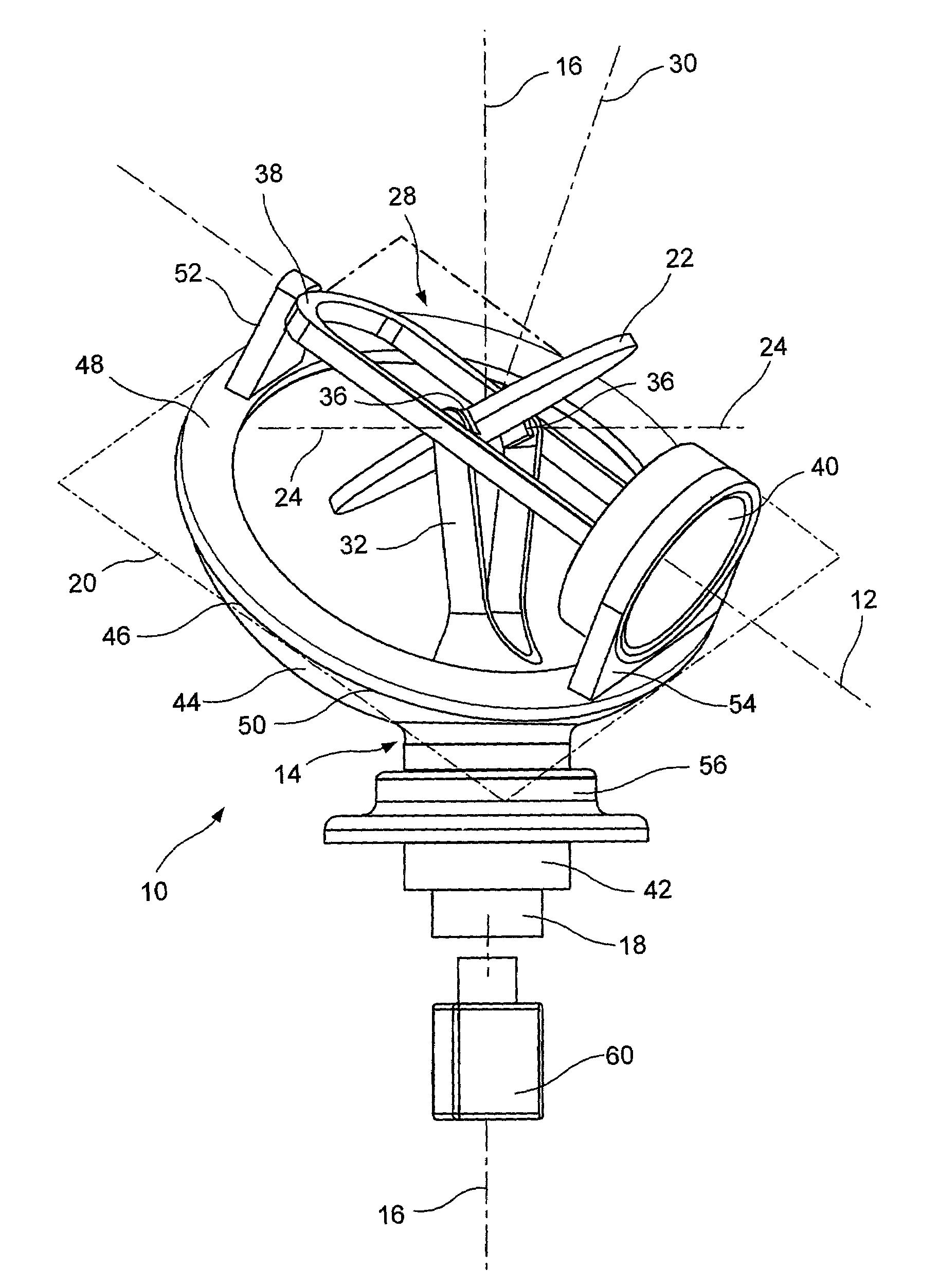
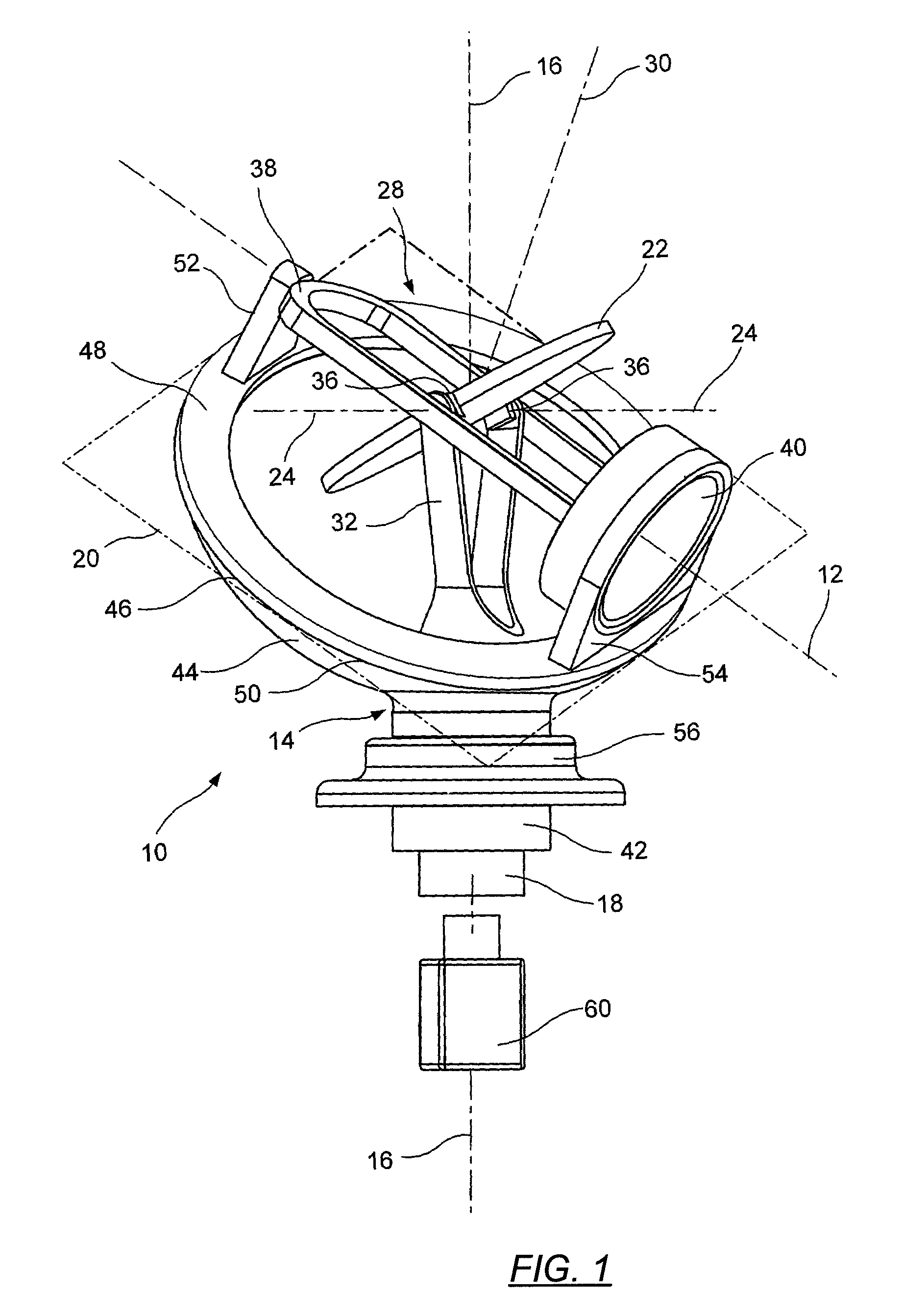
[0040]Referring to the accompanying drawings, there is provided an energy signal processing system 10 for emitting and / or receiving energy signals along a preselected path 12. The processing system includes an outer shaft assembly 14 mounted for rotation about an azimuth axis 16 and an inner shaft assembly 18 coaxially mounted for rotation about the same azimuth axis. The outer shaft assembly extends to define a zenith plane 20, which is inclined with respect to the azimuth axis. It should be understood that the definitions of “azimuth axis” or “zenith plane” only apply in a local frame of reference of the energy signal system. Accordingly, when in use, system 10 can be positioned in any orientation and under any angle with respect to globally defined “azimuth axis” or “zenith plane”.

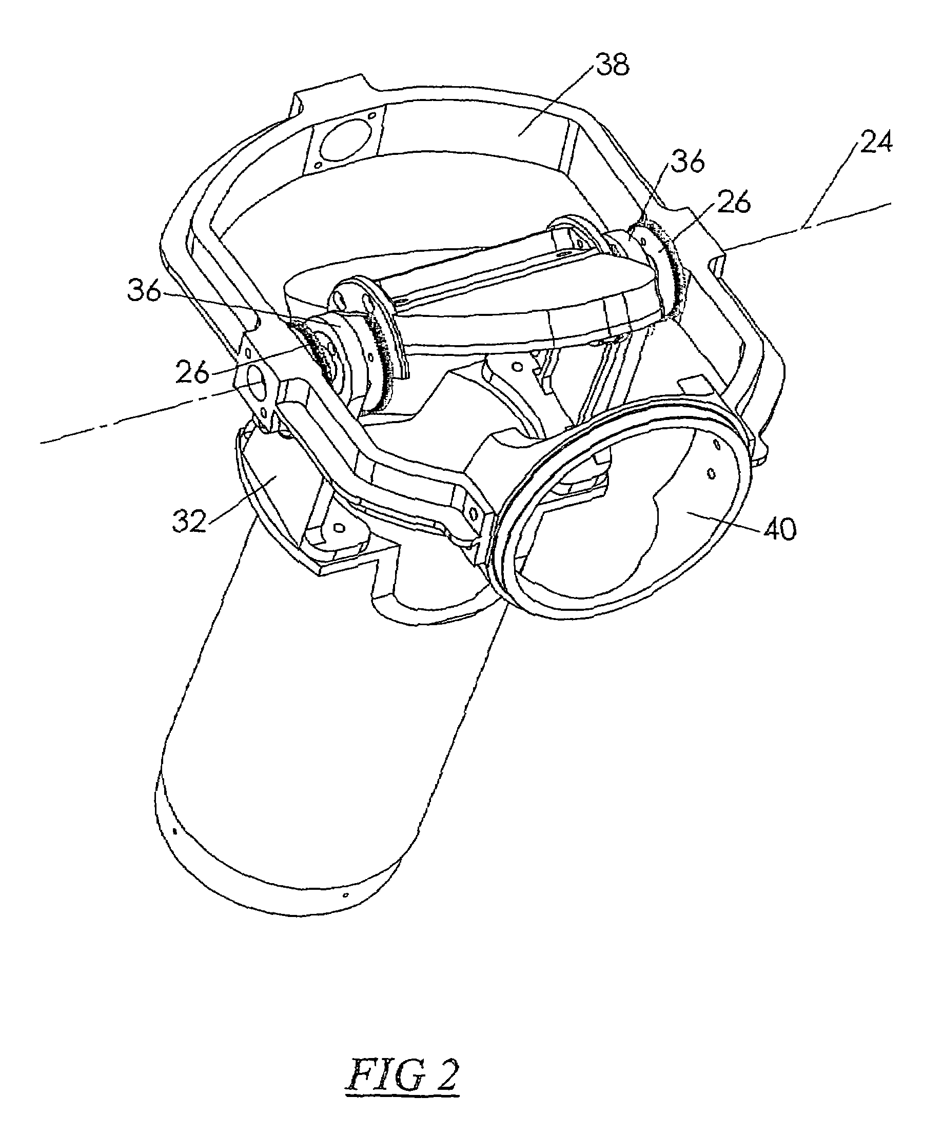
[0041]The energy signal processing element in this preferred embodiment of system 10 is a reflective element 22, in the form of a mirror, that reflects energy signals emitted from an associated emitting...


PUM


Abstract

An energy signal processing system (10) includes a first shaft assembly (14) rotatable about an azimuth axis (16), and a second shaft assembly (18) coaxially mounted for rotation about the azimuth axis (16). The first shaft assembly (14) defines a zenith plane (20) inclined with respect to the azimuth axis (16). The system (10) includes an energy signal processing element (22) rotatable about a processing element axis (24) that intersects and is generally perpendicular to the azimuth axis (16), as well as a means for rotating the element (22) about the element axis (24) such that: energy signals travelling substantially along a preselected path axis (12) and impinging the energy signal processing element (22) are processed or deflected substantially along the azimuth axis (16); or vice versa; or energy signals generated by the energy signal processing element (22) are directed substantially along the preselected path axis (12).

Description

[0001]This application is a continuation of International Application AU2006 / 000754 filed on 2 Jun. 2006, which designated the U.S., claims the benefit thereof and incorporates the same by reference.FIELD OF THE INVENTION[0002]The present invention relates to an energy signal processing system for emitting and receiving energy signals.[0003]The invention has been developed primarily as a device for emitting, receiving and / or simply reflecting signals off an appropriate reflective surface. Thus, while the invention will be described hereinafter with reference to these applications, it will be appreciated that it is not limited to this particular field of use.BACKGROUND OF THE INVENTION[0004]The following discussion of the prior art is intended to place the invention in an appropriate technical context and enable the associated advantages to be fully understood. However, any discussion of the prior art throughout the specification should not be considered as an admission that such art...

Claims


Application Information

Patent Timeline
Patent Type & Authority Patents(United States)
IPC IPC(8): G02B26/10G02B7/198
CPCG01S7/4811G02B7/1827G02B27/644
Inventor BISHOP, MARK VINCENT
Owner OCULAR ROBOTICS
Why Eureka
Try Eureka