
Thermostat operation method and apparatus

a technology of operation method and apparatus, applied in the field of thermostats, can solve the problems of affecting the cooling program time, the limitation of conventional auto thermostats, and the difficulty in programming such a thermosta

Inactive Publication Date: 2010-09-28
TIM SIMON
View PDF52 Cites 280 Cited by
  • Summary
  • Abstract
  • Description
  • Claims
  • Application Information

AI Technical Summary

Benefits of technology

"The invention is about a thermostat that automatically switches between heating and cooling modes based on a user's presence or absence. The thermostat uses sensors to monitor the temperature in a conditioned region and adjust the target temperature accordingly. The method allows for the thermostat to automatically switch between heating and cooling modes based on the user's presence or absence. This can be done by setting the target temperature and sensing the temperature within the conditioned region. The method can also use motion sensors, air pressure changes, and sound levels to determine the user's presence or absence. The user interface of the thermostat allows for easy programming and adjustment of the target temperature. The invention provides a more efficient and effective way to control the temperature in a conditioned region."

Problems solved by technology

In many cases a set of instructions explaining the steps that must be taken to operate the thermostat is printed on the thermostat or separately documented so that programming such a thermostat can be quite confusing and tedious.
There are typically two limitations associated with conventional auto thermostats.
One limitation is that heating and cooling program times must be the same; that is, the times for each period (typically morning, day, evening, and night) must be the same.
The other limitation is that the user's cooling program target temperature can never be closer than X degrees (typically 3° F.) to the user's heating program target temperature.
When the user tries to lower the cooling target temperature below 73, the programming of the thermostat typically just stops and frustrates the user.
Although programmable thermostats hold out the promise of reducing the energy used by heating systems, the U.S. Environmental Protection Agency, which provides the ENERGY STAR certification for appliances and other devices, has expressed concern that potential energy savings are not being realized because of the difficulties consumers face trying to program conventional digital thermostats.

Method used


Image

  • Thermostat operation method and apparatus
  • Thermostat operation method and apparatus
  • Thermostat operation method and apparatus

Examples


Embodiment Construction

[0028]The following description of the invention will typically be with reference to specific structural embodiments and methods. It is to be understood that there is no intention to limit the invention to the specifically disclosed embodiments but that the invention may be practiced using other features, elements, methods and embodiments.

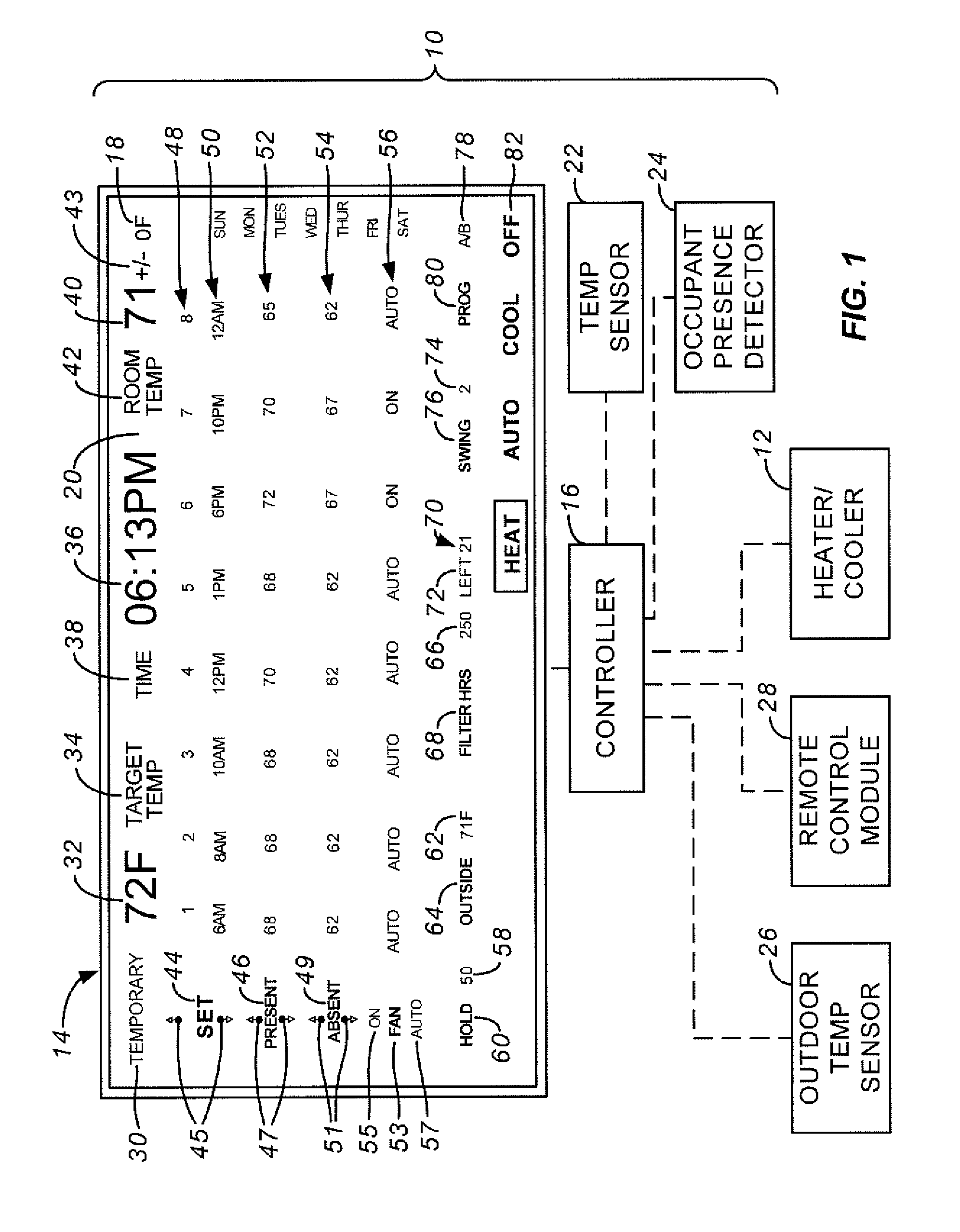
[0029]FIG. 1 illustrates a thermostat 10 connected to a heater / cooler 12. Heater / cooler 12 can include a heating system, a cooling system, or both a heating and cooling system. Heater / cooler 12 typically includes both heating and cooling units. Thermostat 10 may be used with, for example, one or more of gas or electric forced air furnaces, gas or electric radiant heating furnaces, electric forced air air-conditioning systems, and electric heat pumps. The invention may also be suitable for solar or solar electric heating / cooling systems used instead of or in addition to conventional heating and / or cooling systems.

[0030]Thermostat 10 includes a user ...


PUM


Abstract

A thermostat may be placed in a heating mode when the sensed temperature is less than the lowest of the heating and cooling target temperatures by a first amount and may be placed in a cooling mode when the sensed temperature is greater than the highest of the heating and cooling target temperatures by a second amount. The presence or absence of a user may be monitored. If the thermostat is in a user absent mode, a cool setback amount may be added to the cooling target temperature and a heat setback amount may be subtracted from the heating target temperature to arrive at setback cooling and setback heating target temperatures, respectively. The thermostat may comprise a touch-sensitive screen having various display areas.

Description

CROSS-REFERENCE TO RELATED APPLICATIONS[0001]This patent application claims the benefit of provisional patent application No. 60 / 645,083, filed 19 Jan. 2005, entitled Thermostat With Touch-Screen Display, and provisional patent application No. 60 / 664,561, filed 23 Mar. 2005, entitled Water Timer and Method.[0002]This application is related to U.S. application Ser. No. 11 / 335,155, TIMS 1007-3), titled Multiple Thermostat Installation, filed on 19 Jan. 2006.STATEMENT REGARDING FEDERALLY SPONSORED RESEARCH OR DEVELOPMENT[0003]Not applicable.REFERENCE TO MICROFICHE APPENDIX[0004]Not applicable.BACKGROUND OF THE INVENTION[0005]The present invention relates generally to thermostats used for heating and cooling systems, such as gas or electric forced air furnaces, gas or electric radiant heating furnaces, electric forced air air-conditioning systems, and electric heat pumps. Invention may also be suitable for other types of systems, including solar and solar electric heating and cooling sy...

Claims


Application Information

Patent Timeline
Patent Type & Authority Patents(United States)
IPC IPC(8): F25B29/00G05D23/00F24F11/76
CPCF24F11/0012G05D23/1902G05D23/1934F24F11/0086F24F11/0034F24F11/30F24F2110/10F24F2120/10F24F11/61F24F11/88F24F11/67F24F11/39F24F11/523F24F11/63F24F11/56
Inventor SIMON, TIMOTHY M.SMITH, BLAINE M.FISHER, MATTHEW T.
Owner TIM SIMON
Learn More