Method and electronic power supply device for supplying power to a low-voltage load protected by a protective device

a protective device and low-voltage technology, applied in the direction of emergency protective circuit arrangement, emergency protective arrangement for limiting excess voltage/current, electric devices, etc., can solve the problem of low currents that are not adequate for reliably and safely tripping circuit breakers magnetically, and achieve safe and reliable tripping of protective device and increase output current

Active Publication Date: 2010-09-21
PHOENIX CONTACT GMBH & CO KG
View PDF13 Cites 17 Cited by
  • Summary
  • Abstract
  • Description
  • Claims
  • Application Information

AI Technical Summary

Benefits of technology

[0004]Accordingly, the present invention is based on the object of providing an electronic power supply device, a protection device, an auxiliary power supply device and a method for supplying power to a low-voltage load, protected by a protective device, which enable protective devices, particularly electromagnetic circuit breakers, to be rapidly tripped even when electronic power supply devices are used.
[0005]The conceptual core of the invention can be seen in providing measures which ensure that after a fault has been detected, for example a short circuit at the output, a current is supplied for a short period, for example 15 ms, which is of such a magnitude that a protective device can be reliably and quickly tripped. The period for this is selected in such a manner that electronic components, connected loads and feedlines are not damaged and destroyed.

Problems solved by technology

Due to high electrical losses and the great weight, such 50 Hz transformers are more and more frequently replaced by electronic power supply devices such as, e.g. switched-mode power supplies and transformer power supplies clocked at high frequency in industrial power supplies.
Although electronic power supply devices are on the market which can also generate an output current of up to 2.5-times the nominal current for a short time, that is to say up to 4 seconds, these low currents are not adequate for reliably and safely tripping circuit breakers magnetically.

Method used


Image

  • Method and electronic power supply device for supplying power to a low-voltage load protected by a protective device
  • Method and electronic power supply device for supplying power to a low-voltage load protected by a protective device
  • Method and electronic power supply device for supplying power to a low-voltage load protected by a protective device

Examples


Embodiment Construction

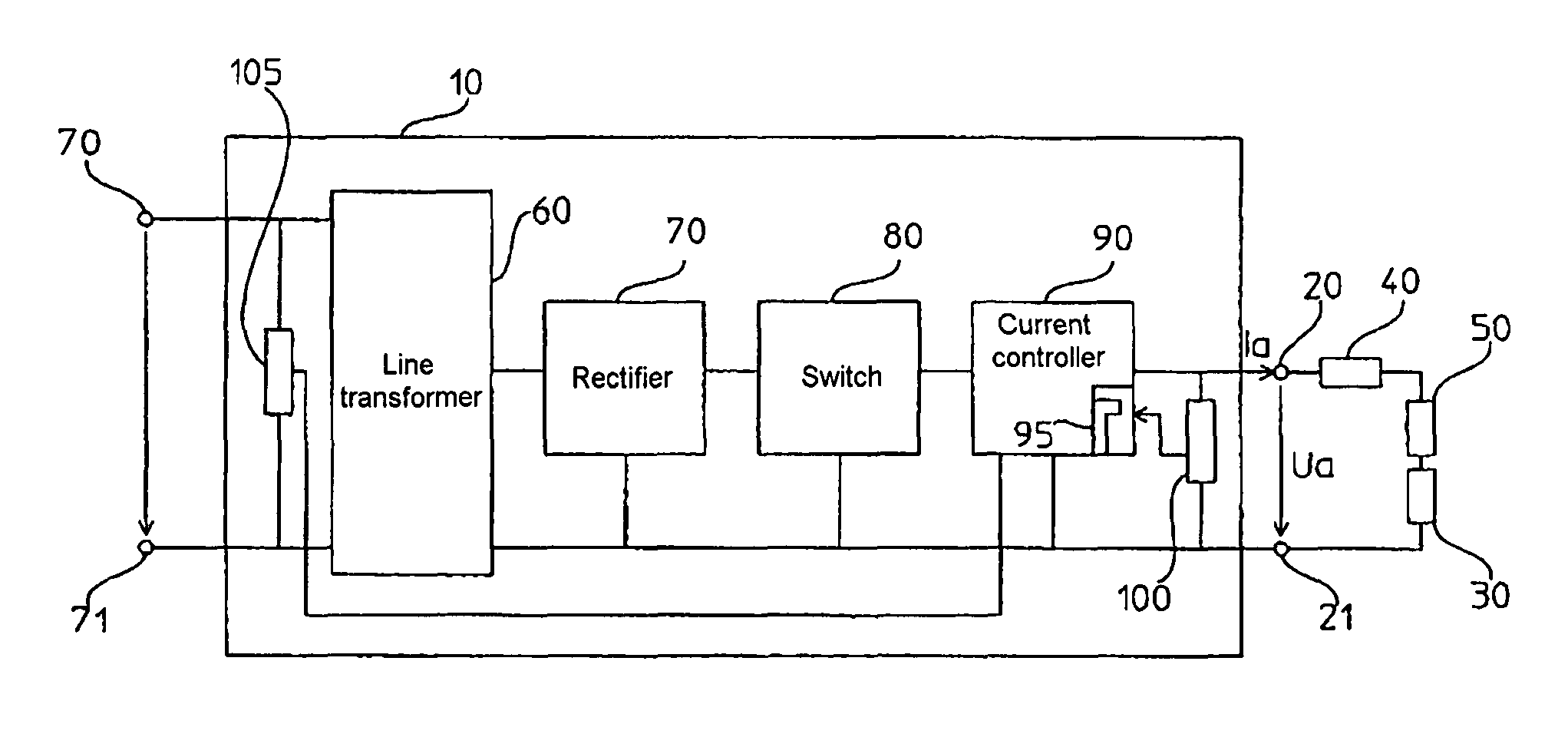
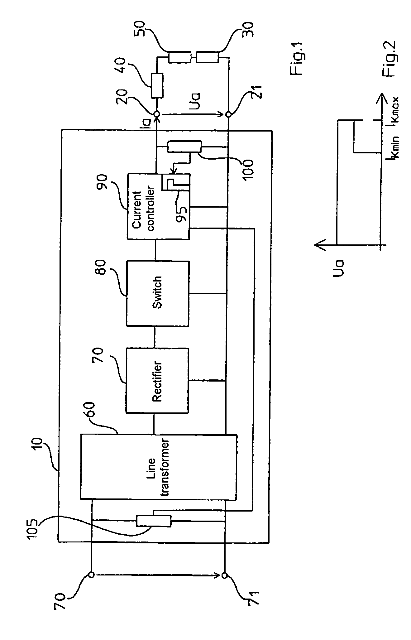
[0028]FIG. 1 shows an exemplary power supply system comprising an electronic power supply device 10, at the output terminals 20 and 21 of which a low-voltage load is connected which is symbolically represented by a resistor 30. The resistance of the feedline to the low-voltage load 30 is taken into consideration by the resistor 40. Furthermore, a protective device, an electromagnetic circuit breaker 50 in the present example, is connected in series with the low-voltage load 30. The electronic power supply device 10 provides, for example, a direct voltage ua of 24 V at the output terminals 20, 21. Although only one low-voltage load 30 is connected to the electronic power supply device 10 in FIG. 1, a number of loads can naturally be connected preferably in parallel to the electronic power supply device 10. A separate circuit breaker can then be allocated to each load.

[0029]The electronic power supply device 10 can be a switched-mode power supply which is supplied via a line voltage U...


PUM


Abstract

The invention relates to an electronic power supply device, particularly a switched-mode power supply, for supplying power to a low-voltage load protected by a protective device, and to a method therefor. The invention also relates to a device for protecting a low-voltage load against an excess current and to an auxiliary power supply device for use with such a protection device. The conceptual core of the invention can be seen in providing measures which ensure that after a fault has been detected, for example a short circuit at the output, a current is supplied for a short period, for example 15 ms, which is of such a magnitude that a protective device can be reliably and quickly tripped. The period for this is selected in such a manner that electronic components, connected loads and feedlines are not damaged and destroyed.

Description

FIELD OF THE INVENTION[0001]The invention relates to an electronic power supply device, particularly a switched-mode power supply, for supplying power to a low-voltage load protected by a protective device, and to a method therefor. The invention also relates to a device for protecting a low-voltage load against an over-current and to an auxiliary power supply device for use with such a protection device.BACKGROUND OF THE INVENTION[0002]In industrial plants, low-voltage loads such as, e.g. controllers, amplifiers and the like, are supplied with a direct voltage of preferably 24 Volts, which is harmless to persons. Suitable power supply devices which provide such a direct voltage can supply output currents of 20 A and more. At such high currents, protection devices such as, e.g. fuses or circuit breakers, must be connected in series with the respective loads in order to protect these and, in particular, the feedlines, against thermal overload and short-circuit currents. In order to b...

Claims


Application Information

Patent Timeline
IPC IPC(8): H02H3/24
CPCH02H3/025H02H3/087H02H3/05
Inventor ZEUCH, JOCHENHENKEL, HARTMUTHEINEMANN, MICHAEL
Owner PHOENIX CONTACT GMBH & CO KG
Why Eureka
Try Eureka