
Corrosion resistant automatic splice

a technology of automatic splicing and corrosion resistance, which is applied in the direction of cable junctions, electrical cable installations, cable fittings, etc., can solve the problems of reducing the service life of aluminum connectors of all types, affecting the service life of aluminum connectors, and preventing their installation in corrosive environments. , to achieve the effect of removing the buildup of corrosive materials in the spli

Active Publication Date: 2010-09-21
HUBBELL INC
View PDF14 Cites 19 Cited by
  • Summary
  • Abstract
  • Description
  • Claims
  • Application Information

AI Technical Summary

Benefits of technology

[0014]Accordingly, an object of the invention is to provide an improved automatic splice for connecting two electrical cables or conductors while eliminating corrosive material buildup within the splice.
[0017]Yet another object of the invention is to provide a splice having a plurality of openings disposed in polar array about the major diameter of the splice for draining liquid from the splice, eliminating corrosive elements and rinsing the splice.
[0018]Still another object of the invention is to provide a cable clamp in the form of an automatic splice, having features and provisions to better withstand exposure to corrosive atmospheres, elements, or environments, thus to extend the reasonable service life thereof.
[0019]A further object of the invention is to provide a cable clamp in which all of the components are compatible from a galvanic perspective to prevent corrosion due to galvanic potential differences within the splice or with the conductor for which it is designed and intended.
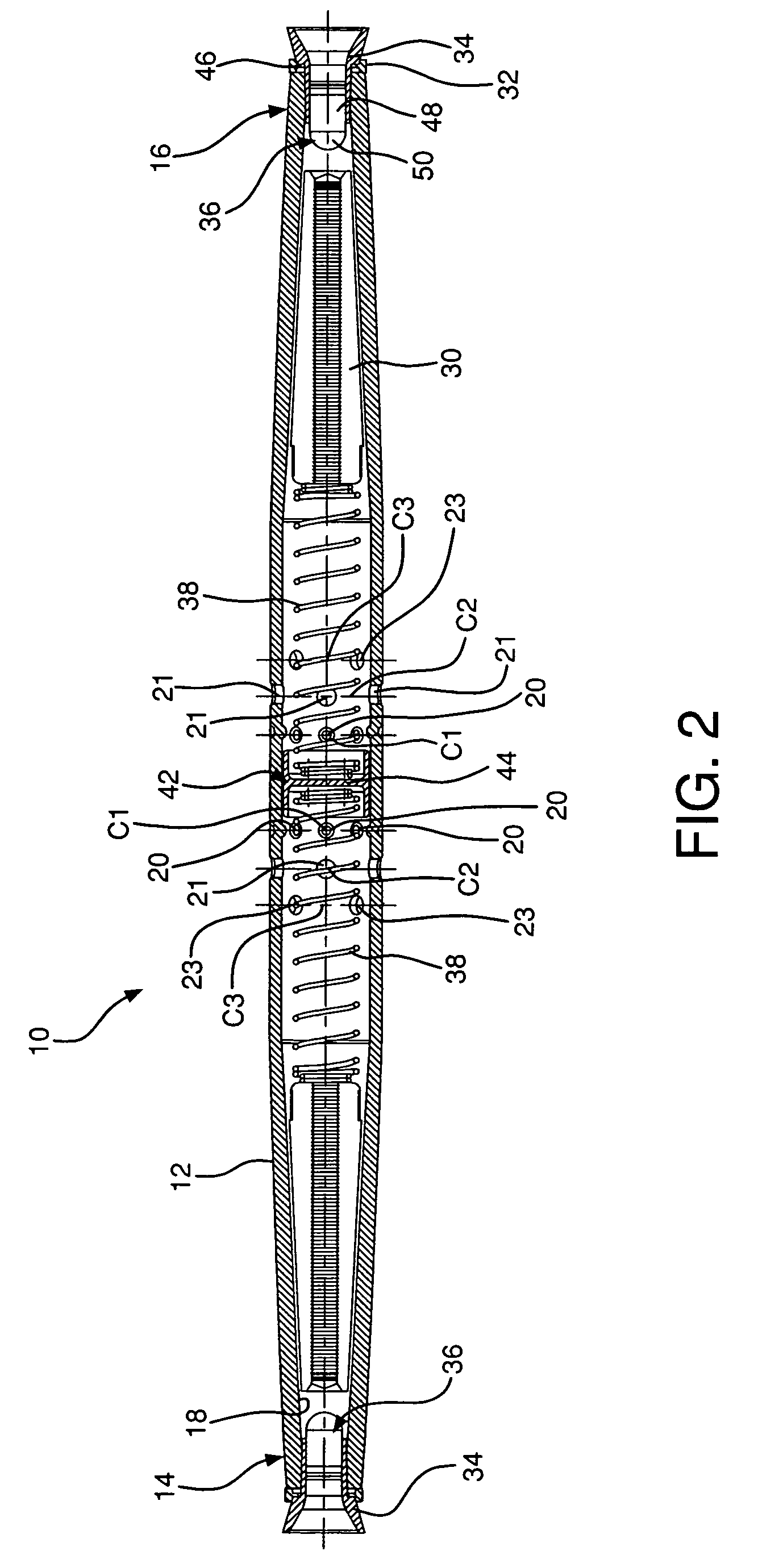
[0020]The foregoing objects are basically attained by providing a clamp for a cable, in the fashion of an automatic splice, having a housing a first end, a second end, and an interior cavity to receive the opposed ends of a cable or electrical conductor. At least two jaws are disposed within the cavity, preferably two sets of jaws located adjacent each opposed end. A biasing member disposed within the cavity biases the jaws towards the first end, and preferably a pair of biasing members, separated by a stopper, located in the approximate center of the body, the stopper supporting the biasing members and providing a positive location for the end of the cable or conductor when installed, and preventing the intrusion of the first cable installed into the cavity to receive the second end or opposed cable, thus assuring that each respective cable end will have sufficient area to be fully installed, its extreme end passing through to the full extent of the gripping jaws, such that complete purchase of the cable or conductor is afforded the clamp.
[0022]A further method of splicing cables includes the steps of feeding an end of a first cable through the first end of a housing and into an interior cavity of the housing and feeding an end of a second cable through an opposite second end of the housing into the interior cavity. The housing tapers towards the first and second ends thereof. The method further involves gripping the first and second cables by first and second pairs of frustoconical clamping jaws on the interior cavity adjacent the first and second ends thereof and passing environmental moisture through a plurality of drainage openings into and out of the housing between the pair of clamping jaws to clean out corrosive agents.

Problems solved by technology

Aluminum, while more economical for construction, suffers more problems associated with corrosion and degradation of the electrical interface over time, in comparison to copper.
In particular, in corrosive environments, such as coastal areas, aluminum connectors of all types experience a reduction in service life.
Along with the aging infrastructure, an abundance of catastrophic failures of aluminum automatic splices in such environments has led a number of electrical utilities which operate and maintain overhead electrical lines in these areas to remove aluminum automatic splices from their approved standards, thus prohibiting their installation in the corrosive environments.
However, the labor and time, and thus the cost of making live line splices with compression tools is unreasonably prohibitive.
Such programs often include cost estimates exceeding twenty times that of installation of automatic splices.
The market has recognized that the view of economics based on purchasing less robust splices with shorter life spans has been a poor choice for the long term.
Thus, the addition of openings in the body of conventional splice designs would violate the required tensile strength.
The plating on such springs does not last long, and consequently, rust begins to form, adding to the corrosive contaminants inside the splice body.
Analysis of the failure mode of aluminum automatics reveals the potential for corrosive elements to build up within the architecture of the device.
As the prominent conductor is constructed with a plurality of strands, wound in a helical manner, it is impractical to attempt to seal the entry port of the connector about the periphery of the conductor, as the interstitial area between the strands will remain as a conduit for moisture to enter the splice body.
In addition, during particularly foggy conditions, the salt fog enters into the body of the automatic splice, due to its open architecture.
Subsequently, following the precipitation event, temperature rise within the automatic splice occurs due to electrical current and solar gain, resulting in evaporation of the water, leaving the corrosive components inside the splice.

Method used


Image

  • Corrosion resistant automatic splice
  • Corrosion resistant automatic splice
  • Corrosion resistant automatic splice

Examples


Embodiment Construction

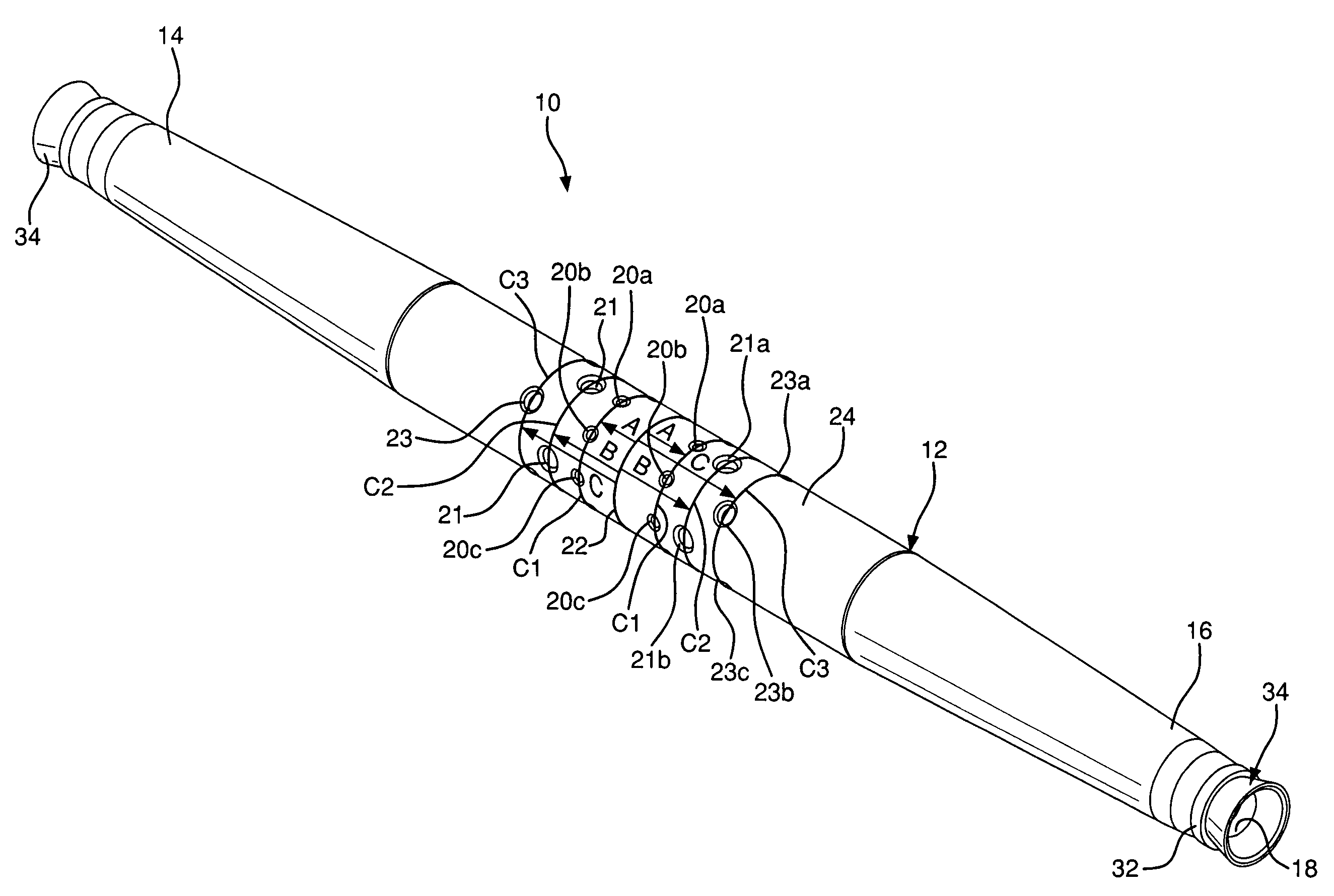
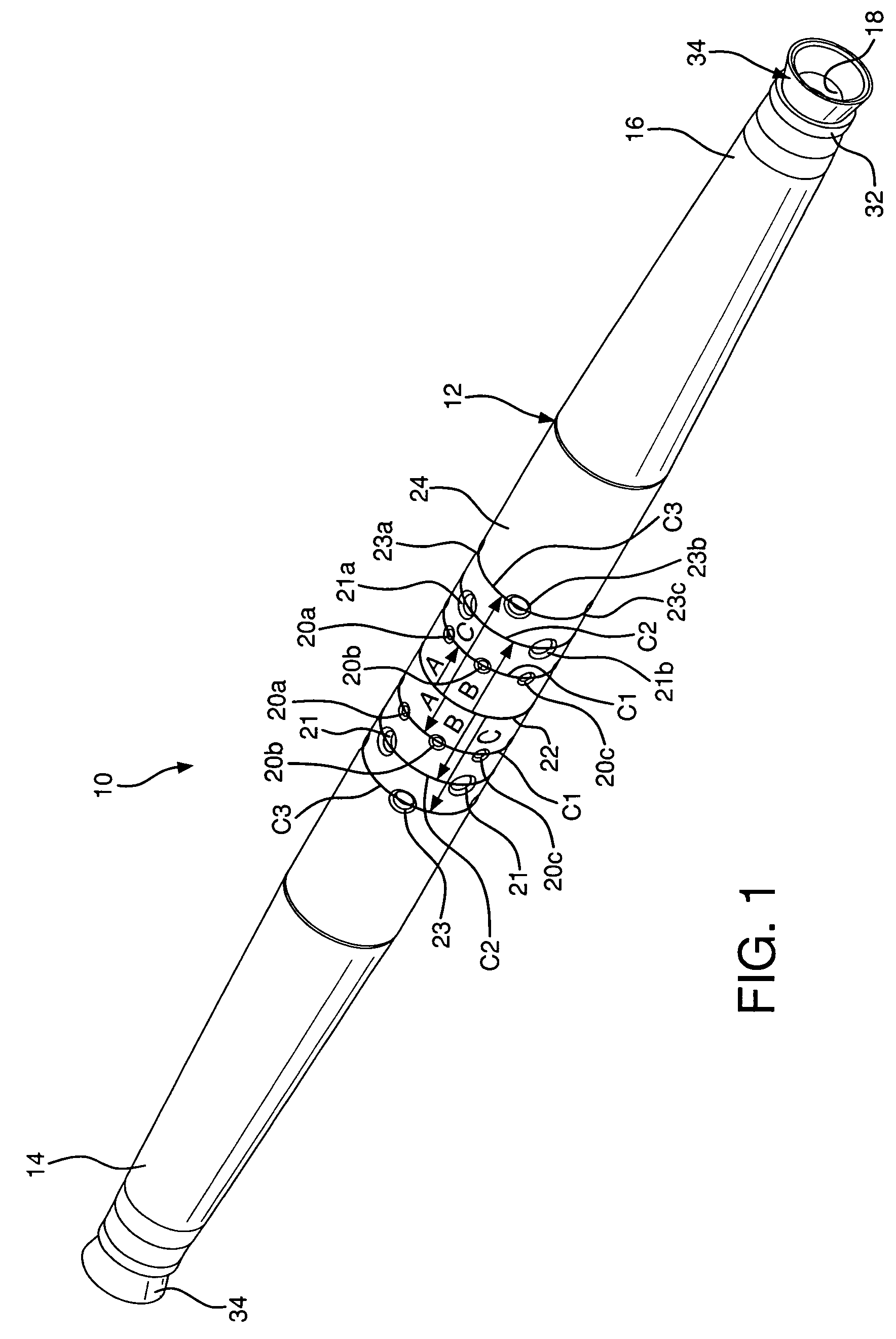
[0031]Turning to FIGS. 1 and 2, a corrosion resistant splice 10 is shown including a housing 12 with a first end 14 and a second end 16, an interior cavity 18 therebetween, a plurality of drainage openings 20, and clamps or jaws 30 at the first and second ends 14, 16 for retaining the cables 40.

[0032]The housing 12 is a tubular body extending along a longitudinal axis with the first end 14 disposed opposite the second end 16. Both ends are conical and taper away from the center 24 of the splice 10. The center section 24 of the splice 10 is defined by the plurality of drainage openings 20 placed in polar array about the major diameter 22 of the splice body 10. This orientation of the openings 20 concentrated towards the middle of the splice 10 allows for rainwater transporting a majority of contaminants and corrosive elements to exit the splice 10 such that the flushing of rainwater rinses the splice 10.

[0033]By designing the splice 10 in this manner, contaminants flowing from one en...


PUM


Abstract

A corrosion resistant automatic splice having a housing with opposed first and second ends, an interior cavity between the ends, and a plurality of drainage openings disposed between an exterior surface of the housing and the interior cavity. The first and second ends are each adjacent a biasing member or spring. A semi frustoconical gripping jaw or clamp is located at each of the first and second ends adapted for receiving a cable. The drainage openings aid in voiding corrosive contaminants from the interior cavity of the splice.

Description

FIELD OF THE INVENTION[0001]The present invention relates to a corrosion resistant automatic splice having a housing with opposed first and second ends, an interior cavity therebetween, and a plurality of drainage openings disposed and extending between an exterior surface of the housing and the interior cavity. A first biasing member is adjacent to the first end and a second biasing member is adjacent to the second end. A tapered gripping jaw is located at each of the first and second ends adapted for receiving a cable.BACKGROUND OF THE INVENTION[0002]Splicing connectors for cables and electrical connectors, commonly referred to as automatic splices, have long been known, and are used by utility linemen to quickly splice lengths of suspended cable together.[0003]The automatic splice has become a mainstay in the electrical utility industry. Originally developed for “emergency restoration”, it has evolved into a nominal construction component for overhead power lines, and has been ex...

Claims


Application Information

Patent Timeline
Patent Type & Authority Patents(United States)
IPC IPC(8): H01R4/00
CPCH01R4/52
Inventor TAMM, R. CARLHAY, ROBERT G.SIEGRIST, STANLEY R.
Owner HUBBELL INC
Learn More