
Electron-blocking layer / hole-transport layer for organic photovoltaics and applications of same

a photovoltaic and electron-blocking technology, applied in the field of photovoltaic devices, can solve the problems of limiting the realization of the maximum theoretical open-circuit voltage vsub, the power conversion efficiency of opv cells is currently too low for them to be used commercially, and the unaddressed need in the art, so as to improve the open-circuit voltage voc of bhj solar cells

Active Publication Date: 2010-09-21
NORTHWESTERN UNIV
View PDF2 Cites 10 Cited by
  • Summary
  • Abstract
  • Description
  • Claims
  • Application Information

AI Technical Summary

Benefits of technology

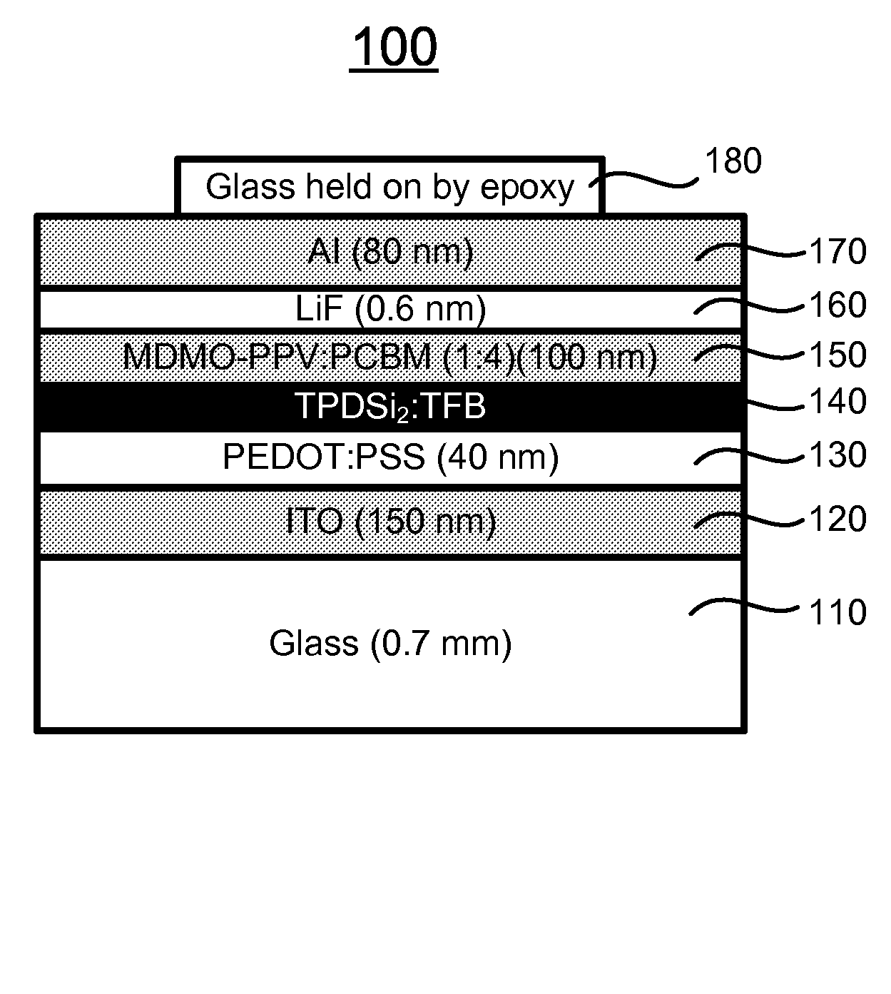
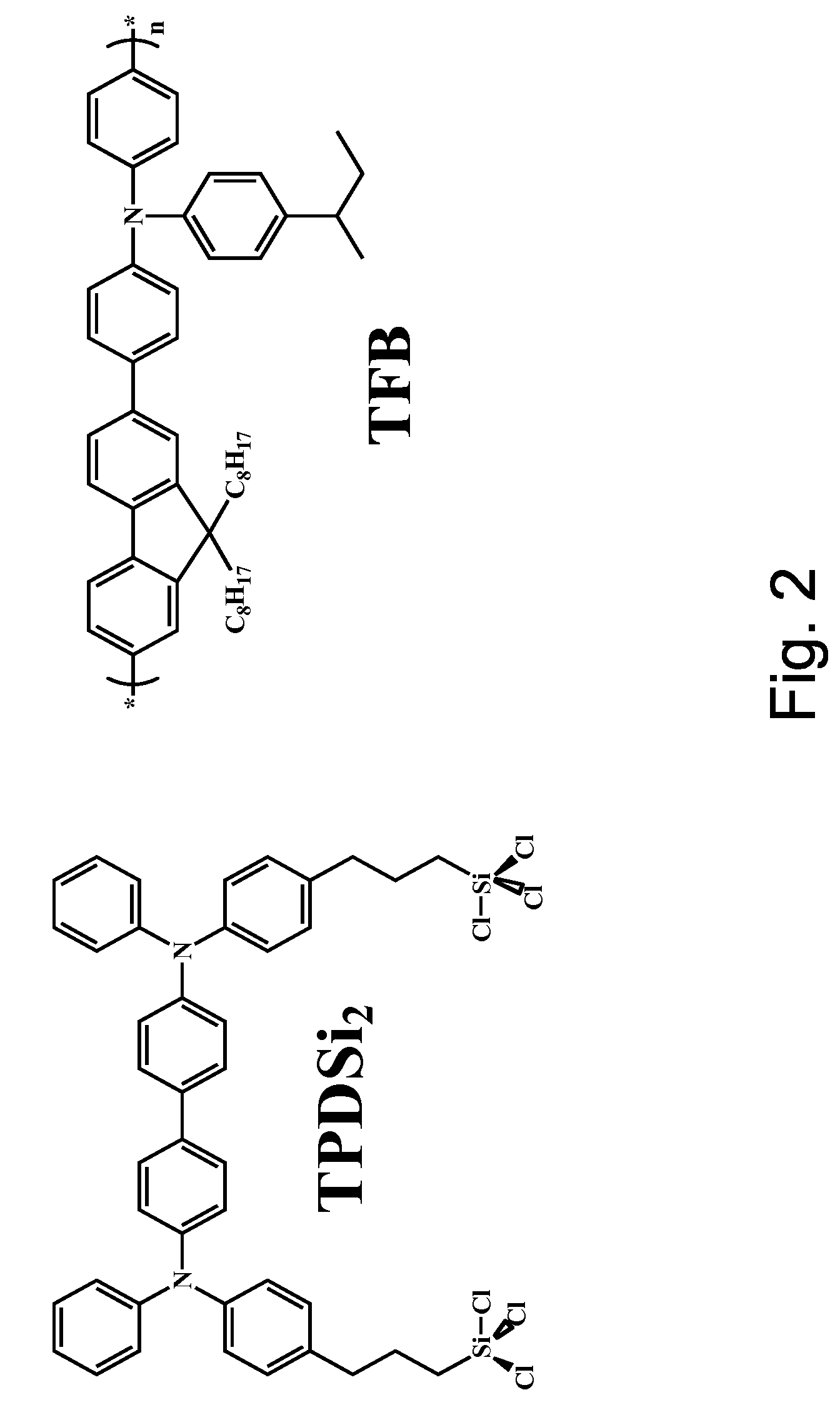
The present invention relates to a solar cell with improved open-circuit voltage (Voc) and an organic photovoltaic device comprising the solar cell. The technical effects of the invention include improving the open-circuit voltage of BHJ solar cells and increasing the efficiency of organic photovoltaic devices. The invention also includes a method of fabricating the solar cell and an organic photovoltaic device with the solar cell. The invention aims to provide a solar cell with a higher Voc, which means it can generate more electricity from sunlight. The invention also includes an electron-blocking layer that prevents electron leakage from the active organic layer to the anode while transporting holes from the active organic layer to the anode. The electron-blocking layer is transparent and made of a hole-transport polymer and a small molecule that has high hole-mobility. The invention also includes a method of fabricating the solar cell and an organic photovoltaic device with the solar cell.

Problems solved by technology

However, the only holdup is that the power conversion efficiency (ηp) of OPV cells is currently too low for them to be used commercially.
In a BHJ solar cell, both the donor polymer and the acceptor molecule are touching both electrodes, interfacial effects probably limit realization of the maximum theoretical open-circuit voltage Voc.
Therefore, a heretofore unaddressed need exists in the art to address the aforementioned deficiencies and inadequacies.

Method used


Image

  • Electron-blocking layer / hole-transport layer for organic photovoltaics and applications of same
  • Electron-blocking layer / hole-transport layer for organic photovoltaics and applications of same
  • Electron-blocking layer / hole-transport layer for organic photovoltaics and applications of same

Examples


Embodiment Construction

[0037]The present invention is more particularly described in the following examples that are intended as illustrative only since numerous modifications and variations therein will be apparent to those skilled in the art. Various embodiments of the invention are now described in detail. Referring to the drawings, like numbers indicate like components throughout the views. As used in the description herein and throughout the claims that follow, the meaning of “a”, “an”, and “the” includes plural reference unless the context clearly dictates otherwise. Also, as used in the description herein and throughout the claims that follow, the meaning of “in” includes “in” and “on” unless the context clearly dictates otherwise. Moreover, titles or subtitles may be used in the specification for the convenience of a reader, which shall have no influence on the scope of the present invention. Additionally, some terms used in this specification are more specifically defined below.

Definitions

[0038]T...


PUM

PropertyMeasurementUnit
thicknessaaaaaaaaaa
thicknessaaaaaaaaaa
temperatureaaaaaaaaaa

Abstract

The present invention, in one aspect, relates to a solar cell. In one embodiment, the solar cell includes an anode; an active organic layer comprising an electron-donating organic material and an electron-accepting organic material; a semiconducting layer formed between the anode and the active organic layer; and an electron-blocking layer (EBL) formed between the semiconducting layer and the active organic layer, where the EBL is transparent and adapted for blocking electron leakage from the active organic layer to the anode while transporting holes from the active organic layer to the anode.

Description

CROSS-REFERENCE TO RELATED PATENT APPLICATION[0001]This application claims the benefit, pursuant to 35 U.S.C. §19(e), of U.S. provisional patent application Ser. No. 60 / 906,456, filed Mar. 12, 2007, entitled “ELECTRON-BLOCKING LAYER / HOLE-TRANSPORT LAYER FOR ORGANIC PHOTOVOLTAICS AND APPLICATIONS OF SAME,” by Tobin J. Marks, Alexander W. Hains, Michael D. Irwin, and He Yan, which is incorporated herein by reference in its entirety.[0002]Some references, which may include patents, patent applications and various publications, are cited in a reference list and discussed in the description of this invention. The citation and / or discussion of such references is provided merely to clarify the description of the present invention and is not an admission that any such reference is “prior art” to the invention described herein. All references cited and discussed in this specification are incorporated herein by reference in their entireties and to the same extent as if each reference was indi...

Claims


Application Information

Patent Timeline
Patent Type & Authority Patents(United States)
IPC IPC(8): H01L31/00
CPCH01L51/4246H01L51/4273H01L51/002H01L51/0037H01L51/0038H01L51/0039H01L51/0043H01L51/0059H01L51/0094H01L2251/308Y02E10/549Y02P70/50H10K71/30H10K85/114H10K85/115H10K85/1135H10K85/151H10K85/631H10K85/40H10K30/353H10K2102/103H10K30/50H10K30/211
Inventor MARKS, TOBIN J.HAINS, ALEXANDER W.IRWIN, MICHAEL D.YAN, HE
Owner NORTHWESTERN UNIV
Learn More