
Two-piece bottom insert for a mold cavity

a mold cavity and bottom insert technology, applied in the field of two-piece bottom inserts for mold cavities, to achieve the effect of reducing heat flow

Active Publication Date: 2010-09-21
MHT MOLD & HOTRUNNER TECH
View PDF12 Cites 10 Cited by
  • Summary
  • Abstract
  • Description
  • Claims
  • Application Information

AI Technical Summary

Benefits of technology

[0011]Taking the above state of the art as the basic starting point, the object of the present invention is to provide a bottom insert which can be easily adapted to varying dimensions of the preform and which as far as possible permits more rapid cooling of the preform in the molding space.
[0014]Furthermore the use of two separate parts means that in general there is automatically a reduced heat flow between the hot part and the cold part.

Problems solved by technology

Even if the shaping surface of the bottom insert should suffer damage in ongoing operation, only the cold part has to be replaced.

Method used


Image

  • Two-piece bottom insert for a mold cavity
  • Two-piece bottom insert for a mold cavity
  • Two-piece bottom insert for a mold cavity

Examples


Embodiment Construction

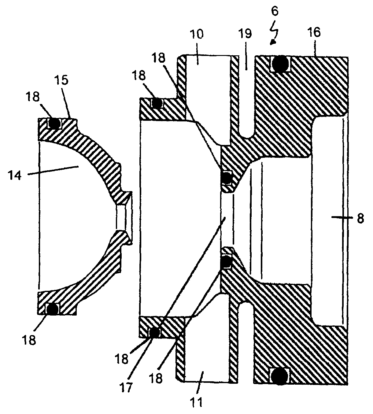
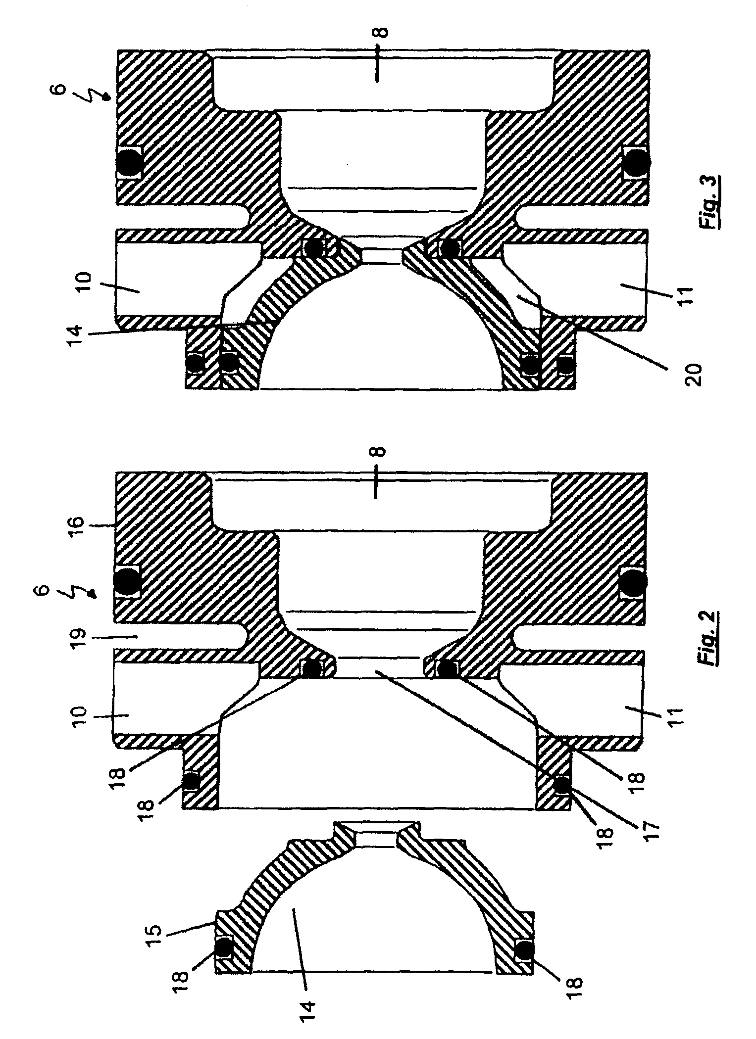
[0020]The hot part is advantageously of such a configuration that it has an opening in opposite relationship to the recess of the hot side, for receiving the cold part. The cold part of the bottom insert is thus fitted into the corresponding recess of the hot part. Sealing integrity of the cold part in relation to the hot part can preferably be effected by means of O-rings.

[0021]It is particularly preferred if all surfaces which are provided for contact with the preform to be produced are arranged at the cold part. It is therefore possible for the cold part to be kept at a relatively low temperature while the hot part is kept at a very high temperature, for example at about 280° C., without the heat loss becoming very great.

[0022]It can further be advantageous if there is provided at the contact surface between the hot part and the cold part, applied to at least one part, an insulating coating, an insulating membrane and / or a spacing element. That measure provides that the transmiss...


PUM

PropertyMeasurementUnit
temperatureaaaaaaaaaa
pressureaaaaaaaaaa

Abstract

A bottom insert for an injection mold, which insert is of a two-part configuration having a hot part which has a recess of the hot side and a cold part which has a recess of the cold side, wherein the cold part is arranged at least partially within the hot part so that the hot part at least portion-wise surrounds the cold part. The two parts of the bottom insert are preferably separable and the. hot part preferably has an opening in opposite relationship to the recess of the hot side for receiving the cold part. Further, the cold part and the hot part are desirably sealed off relative to each other, desirably by O-rings. In general, all surfaces which are provided for contact with the molding to be produced are arranged at the cold part. An insulating coating, an insulating membrane and / or a spacing element is desirably provided at the contact surface between the hot part and the cold part.

Description

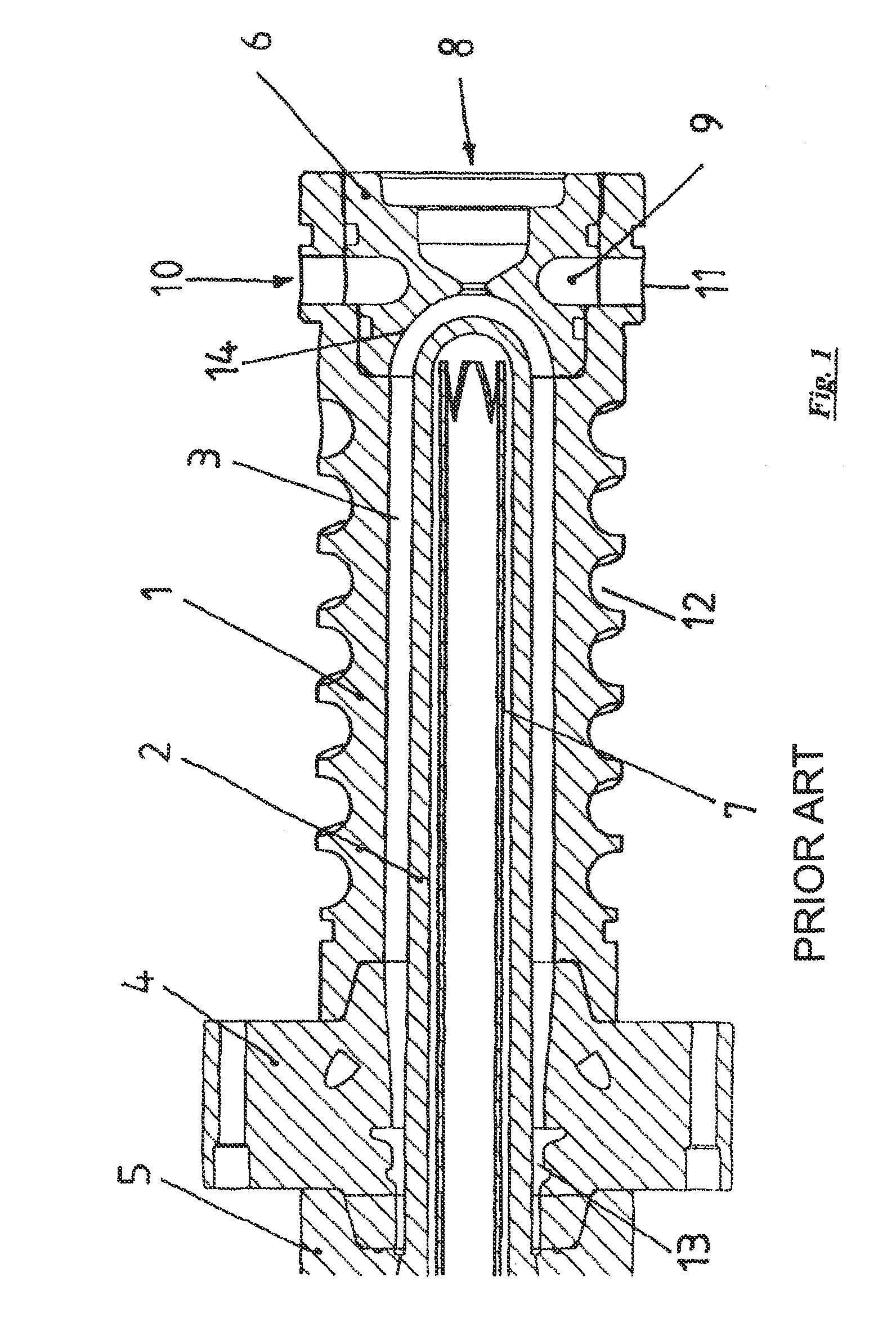
BACKGROUND OF THE INVENTION[0001]The present invention concerns a bottom insert for a mold cavity for the production of moldings of plastic material comprising a main body with a hot side which has a recess for receiving molten plastic material under pressure and a cold side having a recess, the inside contour of which is intended to come into contact with the molding to be produced and to shape the outside contour thereof, and a gate which connects the recess of the hot side to the recess of the cold side and is intended to introduce molten plastic material from the hot side into the cold side.[0002]A mold cavity having such a bottom insert is known for example from DE 100 24 625 and is shown in FIG. 1.[0003]The mold cavity is essentially used in the injection molding process. In injection molding the molding material which is in powder form or granulated is plasticised for example in a screw injection molding machine and then urged for example by axial displacement of the screw th...

Claims


Application Information

Patent Timeline
Patent Type & Authority Patents(United States)
IPC IPC(8): B29C45/73
CPCB29C45/2711B29C45/2737B29C45/73B29K2105/253B29C2033/023B29C2045/7343
Inventor NETER, WITOLDTHOMMES, HELMUTSCHWEININGER, STEFAN
Owner MHT MOLD & HOTRUNNER TECH
Learn More