Eureka AIR delivers breakthrough ideas for toughest innovation challenges, trusted by R&D personnel around the world.

Automated dispenser with sensor arrangement

a dispenser and sensor technology, applied in the field of dispensers, can solve the problems of difficult user's hand distinguishing from the background ir, dispensing to occur, and problems such as the amount of power used, and achieve the effect of less power and less power

Inactive Publication Date: 2010-09-14
SCA HYGIENE PROD AB
View PDF71 Cites 41 Cited by
  • Summary
  • Abstract
  • Description
  • Claims
  • Application Information

AI Technical Summary

Benefits of technology

[0016]The invention provides a means of improving detection reliability by compensating for background IR levels of increasing or decreasing intensity by means of varying the current supplied to the IR emitter(s), thereby varying the amount of emitted IR used by the sensing system. One way of doing this is when general background IR levels are generally high, the power sent out by the IR emitters is made higher by increasing the current passed through the IR emitter. Thus, a user approaching the dispenser in bright light conditions will more easily be detected, since the amount of reflected IR compared to background IR will be larger than if no current change had been made. Therefore, the difference between received IR from reflection off the user's hand compared to background IR will be greater, and thus the user's hand will be readily detected, which is particularly advantageous when the user's hand is less white due to the lower IR reflection obtained.
[0032]Advantageous use can be made of the varied scanning rate by making the first scanning rate between e.g. 0.15 and 0.25 seconds between scans (i.e. the scanning rate when a possible user is outside the first detection zone) or even longer (such as between 0.25 seconds and 0.5 seconds), and the second scanning rate of the order of about 0.08 to 0.12 seconds between scans and requiring only two consecutive scans (or e.g. two out of three consecutive scans) providing a reflected IR level above background IR level to activate dispensing. Such dispensing will be perceived as almost immediate, yet a significant amount of power used by the sensor system can be saved due to the initial low scanning rate which consumes less power.

Problems solved by technology

In the aforementioned dispenser, although a certain degree of compensation is made for background light levels which can take account of some conditions, problems will arise in such a device due to temporary effects of high IR changes due to atmospheric conditions, in particular when background IR is very low, since only very small changes in reflected IR can cause dispensing to occur even when not required.
Likewise, the problem would also be encountered that as background IR levels generally increase to a high level, a user's hand becomes harder to distinguish against the background IR because the increased level of IR due to the IR reflection from a user's hand, when the hand is in front of the dispenser, may be approximately at the same level as the background IR, or due to the temporary blocking of the high level background IR, the presence of a hand can even reduce the level to below that of background IR received in the IR sensor, such that the hand in many cases is not reliably detected.
This can result in lack of hygiene when several users consecutively touch the dispenser.
Further, while the IR emitted intensity from the emitter is seemingly constant in the aforesaid document (apart from possible variations to low battery voltage), such a construction when relying on battery power from batteries (rather than solar cells) often involves using unnecessarily high power.

Method used


Image

  • Automated dispenser with sensor arrangement
  • Automated dispenser with sensor arrangement
  • Automated dispenser with sensor arrangement

Examples


Embodiment Construction

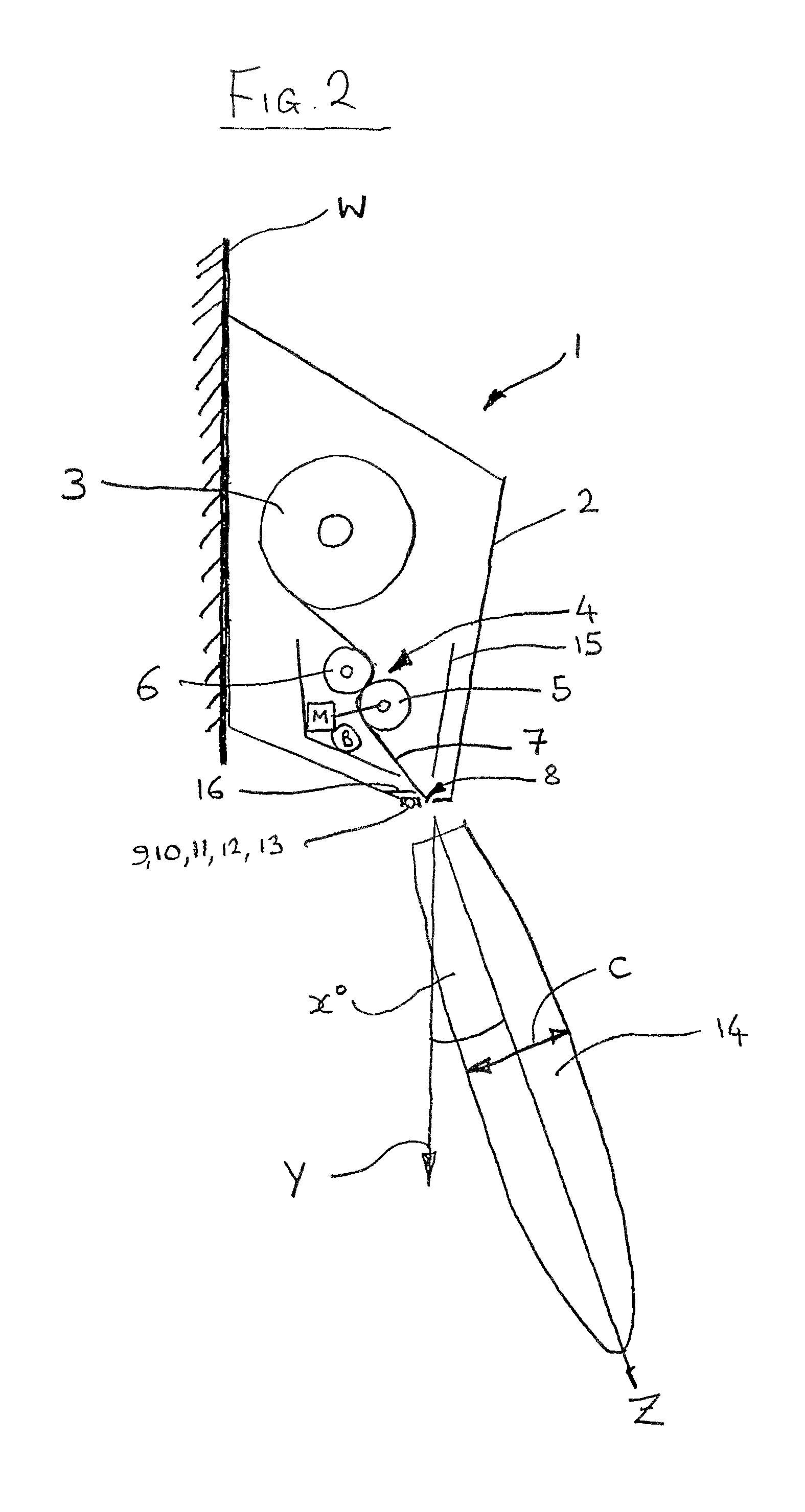
[0044]FIG. 1 and FIG. 2 show a dispenser 1 in front and side views respectively, whereby FIG. 2 shows the dispenser 1 attached at its rear side to a wall W (the means of attachment are not shown but may be of any suitable type such as screws, adhesive, or other attachment means), whereby the rear surface of the dispenser lies against said wall W which is normally vertical.

[0045]The dispenser 1 comprises a housing 2, within which is located a product supply, in this case a supply of paper in a roll 3. The roll 3 is suitably a roll of continuous non-perforated paper, but may also comprise perforated paper. Also located in the housing 2 is a paper transport mechanism 4 preferably in the form of a modular drive cassette with its own casing 15, which can preferably be removed as a single unit from the housing 2 when the housing is opened.

[0046]FIG. 1 shows the paper roll 3 and the transport mechanism 4 which feeds paper from the roll towards a discharge outlet (see further description be...


PUM


Abstract

An automatic electrically powered dispenser for dispensing a product stored in the dispenser includes an active IR sensor system for detecting a user. The IR sensor system includes at least one IR emitter and at least one IR receiver. The IR sensing system is arranged to scan for the presence of a possible user at a certain scanning rate. A sensor control system supplies the active IR emitter(s) with a first current which is constant during one or more single scans and is altered to a different, second current for further scanning. The first and second currents are determined on the basis of a signal strength of the average received IR which is received by the IR receiver(s) during a number of previous single scans. In a simplified system, the average value of the most recently received IR values may be compared to a standard value set in the control system to alter the current supplied to the IR emitter(s).

Description

CROSS REFERENCE TO RELATED APPLICATION[0001]This is a continuation of international application PCT / EP2005 / 007616 filed on 13 Jul. 2005, which designated the United States of America.FIELD OF THE INVENTION[0002]The present invention relates generally to a dispenser having an active infrared (IR) sensor system, in particular for dispensers of the type including a motor-driven dispensing system combined with control circuitry for sensing the presence of a possible user by means of said IR sensor system and controlling operation of said motor to effect dispensing of material.[0003]The invention furthermore relates particularly to an automatic towel dispenser (preferably with paper towels stored inside the dispenser housing) of the electrically powered type, preferably a battery powered type (but which could also be AC powered or powered by a combination of AC and DC power supplies), in which the IR sensor system is used to control dispensing of products such as paper sheets (e.g. paper...

Claims


Application Information

Patent Timeline
Patent Type & Authority Patents(United States)
IPC IPC(8): H01L27/00
CPCA47K10/36H03K17/943H03K2217/94116H03K2217/94031H03K2217/94108H03K2217/94026A47K10/3612A47K10/3625A47K2010/3668Y10T225/205Y10T225/206Y10T225/21
Inventor MOK, KIN LUNMOK, KING LUNNG, HONG
Owner SCA HYGIENE PROD AB
Why Eureka
Eureka Blog
Learn More