
Guidance system with varying error correction gain

a technology of error correction gain and guidance system, which is applied in the direction of direction controllers, target-seeking control, instruments, etc., can solve the problems of inaccuracy of expected bearing to the point of intersection, error or tolerance in the accuracy of such knowledge, and inherent error or tolerance in the output of guidance control

Inactive Publication Date: 2010-09-14
LOCKHEED MARTIN CORP
View PDF28 Cites 12 Cited by
  • Summary
  • Abstract
  • Description
  • Claims
  • Application Information

AI Technical Summary

Benefits of technology

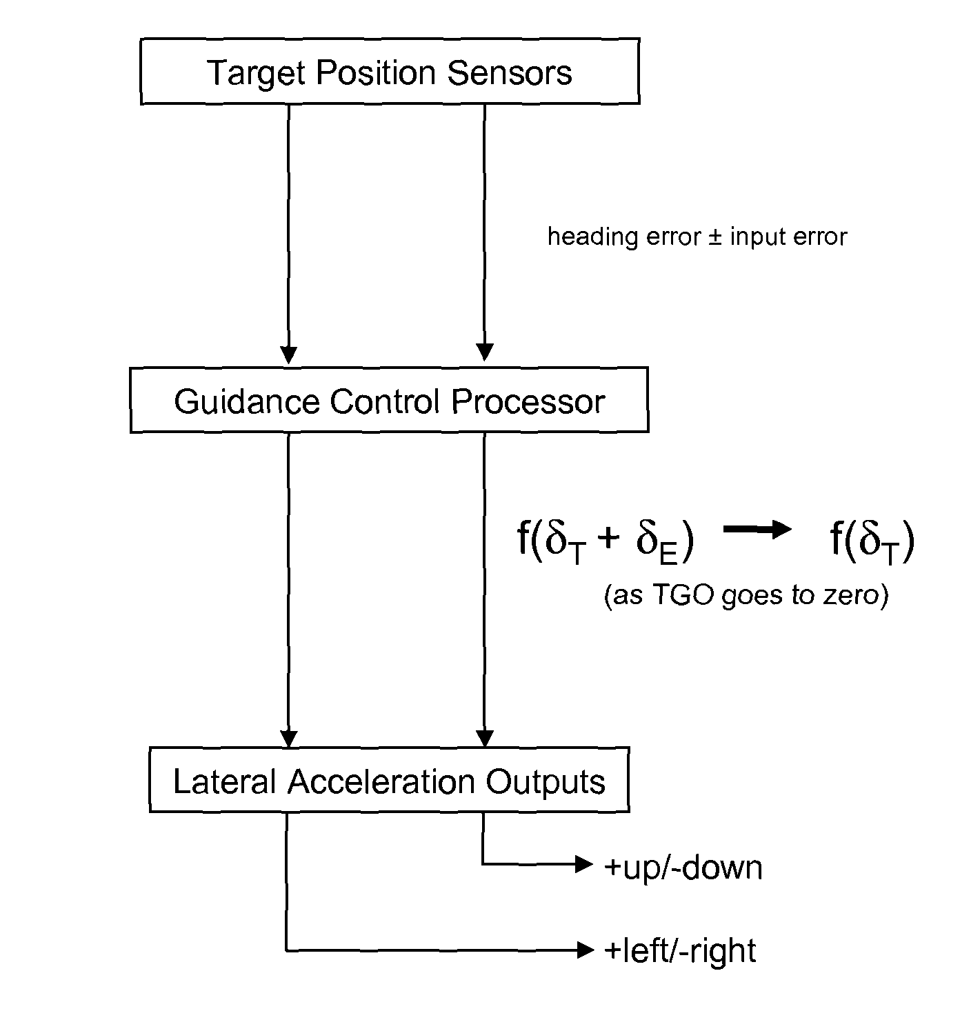
The present invention provides a guidance system and control law that can respond robustly to valid heading errors and less robustly or not at all to invalid errors caused by noisy or inaccurate input data. The guidance law re-computes guidance data according to a schedule, such as at each update of input values, to determine the direction and amplitude of lateral acceleration needed to redirect the missile or other guided vehicle toward a state where it will intersect the re-calculated trajectory of the target. The guidance law compensates for detected heading error that is dominated or affected by random input error, but not true bias. The controller and control method repetitively predict the trajectory of the target, plot an intersecting missile trajectory to a point of intersection, and apply acceleration as necessary, in a direction perpendicular to a line of sight from the missile to the point of intersection. The amount of acceleration can be related to the extent of error by a proportional or other function, for example damped to minimize overshoot. The acceleration can be applied using controlled outputs such as devices for redirecting thrust, movable aerodynamic control surfaces or other steering arrangements, lateral acceleration devices such as steering thrusters. The corrective acceleration function is adjusted as interception approaches to compensate for the increasing contribution of random noise in the assessment of heading error as point of interception approaches.

Problems solved by technology

An error between the current missile trajectory versus a desired missile trajectory to intersect with the target, is identified when the bearing to the target differs from the expected bearing to the target, leading to a conclusion that the expected bearing to the point of intersection is not accurate.
There is some inherent error or tolerance in the accuracy of such knowledge, for example, the relative bearing of the target, or its range or velocity vector, or the like.
There also is some inherent error or tolerance in the guidance control outputs.
In a typical guidance system, inherent input and output errors are taken in stride.
The guidance law will produce erroneous control accelerations if the input data is not accurate.
This reduces the responsiveness of the control.
If a large threshold is chosen, input errors can be introduced.
There is little practical alternative other than to rely on the input data that is available.
Absolute input accuracy cannot be expected in the practical world.
Some error in defining the missile and target states will be encountered and will affect the accuracy and success of the guidance law.
The effect of an input error is that the guidance law seeks to adjust the missile flight path to intersect an erroneously predicted intercept point along the trajectory of the target.
On the other hand, the target may change speed or heading, or the trajectory of the missile may be affected by external influences.
Noise may cause the guidance control to alter the trajectory in a given direction away from an accurate heading leading toward target interception.
Assuming that errors continue to arise randomly, the result can be unnecessary steering movements.
Unnecessary steering movements reduce the speed of the missile and detract from the mission.
However, a variance in an input value due to noise may be difficult to distinguish from an effect to which the guidance system should respond, such as evasive movements of an independently guided target.
As discussed, this reduces the responsiveness of the guidance system to changes in input conditions such as evasive movements of the target.
Fuzzy logic controls generally reduce the incidence of wide control swings by imposing rules, but in so doing also reduce the potential responsiveness of a control.
This technique also renders the guidance system less accurate and responsive to the target, because the next previously computed way point may not be an optimal way point in view of changed conditions.

Method used


Image

  • Guidance system with varying error correction gain
  • Guidance system with varying error correction gain
  • Guidance system with varying error correction gain

Examples


Embodiment Construction

[0034]A novel technique for noise tolerant guidance as disclosed herein seeks to evaluate the commands that result from application of an applicable guidance law. The technique is applicable to various specific guidance laws and is discussed in the example of a feedback error control function.

[0035]A basic input to a guidance control system is provided by sensor data signal provided continuously or sampled successively and reported over time to a guidance controller such as a processor, identifying the present position of a target to be intercepted. In one embodiment, the position information is limited to identification of a line of sight to the target. Referring to FIG. 1, a missile or projectile is assumed to be located at the origin of the orthogonal X-Y-Z axes shown (axis Z being perpendicular to the X-Y plane). In different embodiments, the guided item might be a self propelled missile such as a rocket, or the invention could be applied to control of a projectile such as an ar...


PUM


Abstract

A guided missile or projectile and associated guidance control are provided to control a path to a point of intersection with a potentially moving target. A new path is repetitively recomputed and acceleration orthogonal to the path is applied to minimize heading error and thereby to converge on the target. The gain of the control function is partly proportional to heading error, but the gain is reduced approaching the point of convergence. In this way, the guidance control is more responsive to actual variance of the true heading error and is less responsive to random error in sensing the target heading, which random error would otherwise increase in its contribution to corrective guidance movements approaching the point of intersection.

Description

GOVERNMENTAL INTEREST[0001]This invention was made with government support under Contract / Grant Aegis N00024-03-C-5115. The United States Government has a non-exclusive, non-transferable, paid-up license in this invention.BACKGROUND[0002]1. Field[0003]The invention relates to the field of guidance control systems, providing a method and apparatus for dynamically guiding a controlled item such as a guided missile or guided projectile, toward intersection with the target at a location such as a point along a potentially changing trajectory of the target.[0004]2. Related Art[0005]Various guidance systems are possible for directing a guided missile, projectile or other moving item toward a destination by use of corrective lateral acceleration. In a case where the destination is a stationary point, there may be uncertainty in fixing the location of the target, which advantageously is decreased as the missile or projectile approaches the target. The trajectory of the guided item may be in...

Claims


Application Information

Patent Timeline
Patent Type & Authority Patents(United States)
IPC IPC(8): F41G7/22F42B15/01F42B15/00F41G7/00
CPCF41G7/22G05D1/12F42B15/01
Inventor BOCK, GREGORY F.
Owner LOCKHEED MARTIN CORP
Learn More