Mounting assembly for adjustably mounting frame parts onto wall or into wall opening, enabling positional adjustment of frame part in multiple directions

a technology for mounting parts and frame parts, which is applied in the direction of building components, building scaffolds, domestic objects, etc., can solve the problem of limiting the extent to which the mounting assembly can be tilted and achieve the maximum adjustment of the orientation, overcome small surface irregularities of the reveal wall, and enhance the adjustment of the orientation of the holder element with respect to the reveal wall

Inactive Publication Date: 2010-09-14
INDOOR COLLECTION NV
View PDF29 Cites 5 Cited by
  • Summary
  • Abstract
  • Description
  • Claims
  • Application Information

AI Technical Summary

Benefits of technology

[0008]An analysis of the problem of the prior art mounting assembly has shown that the problem is partly caused by the fact that the mounting assembly is fixed to the reveal wall on two spaced apart locations. This limits the extent to which the mounting assembly can be tilted with respect to the reveal wall. In the mounting assembly of the invention, this limit is removed by applying only one fixing element for fixing the assembly to the reveal wall. Furthermore, by providing the pivot which enables the holder element to pivot with respect to the fixing element, the adjustability of the orientation of the holder element with respect to the reveal wall is severely enhanced.
[0009]The mounting assembly of the invention preferably comprises adjustment means on at least three spaced apart locations at the periphery of the holder element. This ensures that the holder element can be tilted in all directions with respect to the fixing element and the reveal wall. The fixing element is preferably located substantially in the centre of the holder element, i.e. as far as possible from the locations where the adjustment means are provided. This ensures that the tilting of the holder element can be effected to a large extent. This whole arrangement can ensure a maximum adjustability of the orientation of the holder element with respect to the reveal wall.
[0010]The holder element of the mounting assembly of the invention preferably has an inner part which carries the attachment means for attaching the frame part and which movably engages the fixing part in such a way that the inner part enables an adjustment in distance towards the reveal wall. By means of this arrangement, the distance between the attachment means and the reveal wall, and thus the distance between the frame part attached to the mounting assembly and the reveal wall can be adjusted, at least to a small extent. This adds an additional degree of freedom to the mounting assembly of the invention, so that substantially all the surface irregularities which the reveal wall may have can be overcome.
[0011]For bridging larger distances between the frame part and the reveal wall, the mounting assembly of the invention may further comprise one or more spacer elements in a flexible material, which are provided for placement between the holder element and the reveal wall. The flexibility of the spacer elements helps to overcome small surface irregularities of the reveal wall and to dampen vibrations, leading to a more rigid attachment of the frame part to the reveal wall.

Problems solved by technology

An analysis of the problem of the prior art mounting assembly has shown that the problem is partly caused by the fact that the mounting assembly is fixed to the reveal wall on two spaced apart locations.
This limits the extent to which the mounting assembly can be tilted with respect to the reveal wall.

Method used


Image

  • Mounting assembly for adjustably mounting frame parts onto wall or into wall opening, enabling positional adjustment of frame part in multiple directions
  • Mounting assembly for adjustably mounting frame parts onto wall or into wall opening, enabling positional adjustment of frame part in multiple directions
  • Mounting assembly for adjustably mounting frame parts onto wall or into wall opening, enabling positional adjustment of frame part in multiple directions

Examples


Embodiment Construction

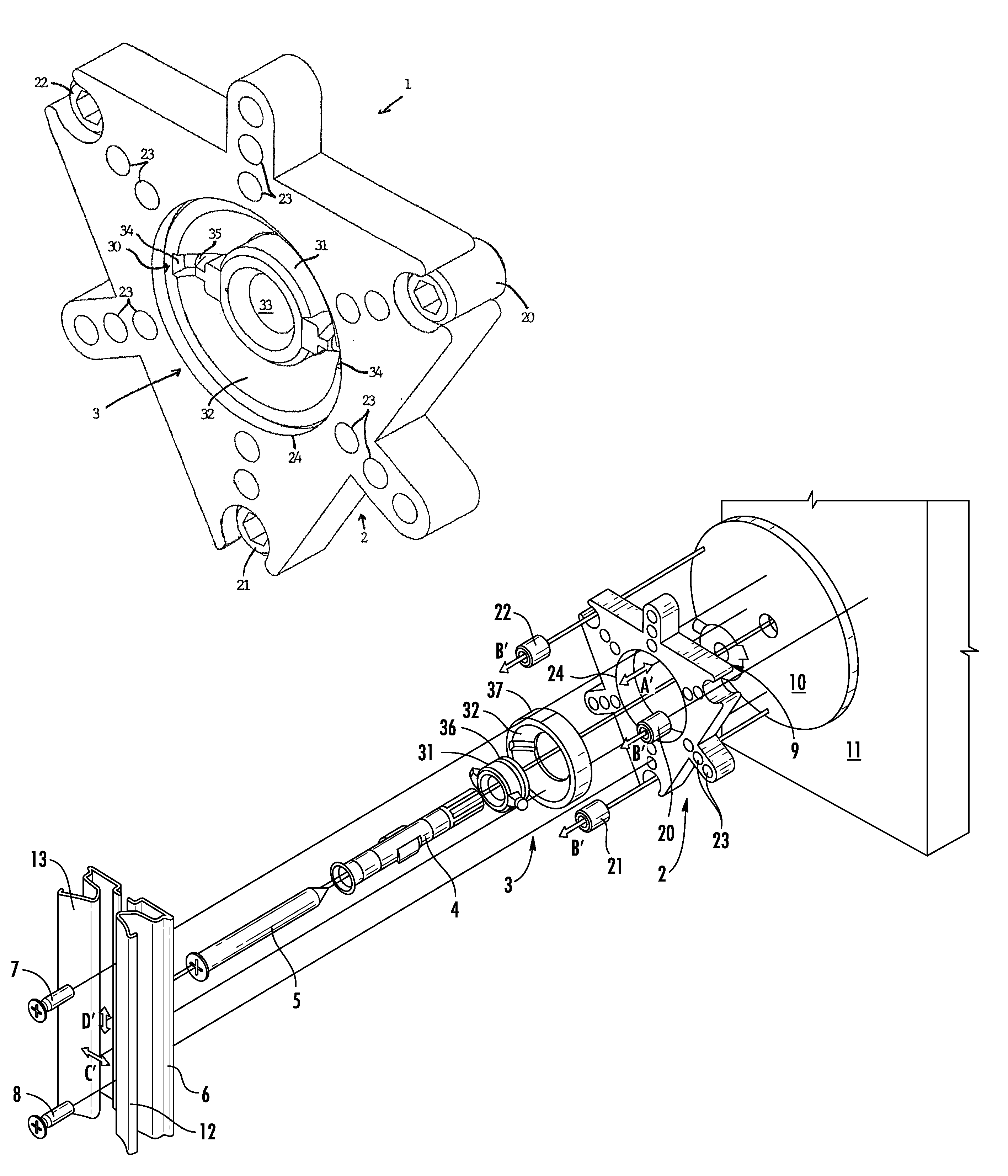
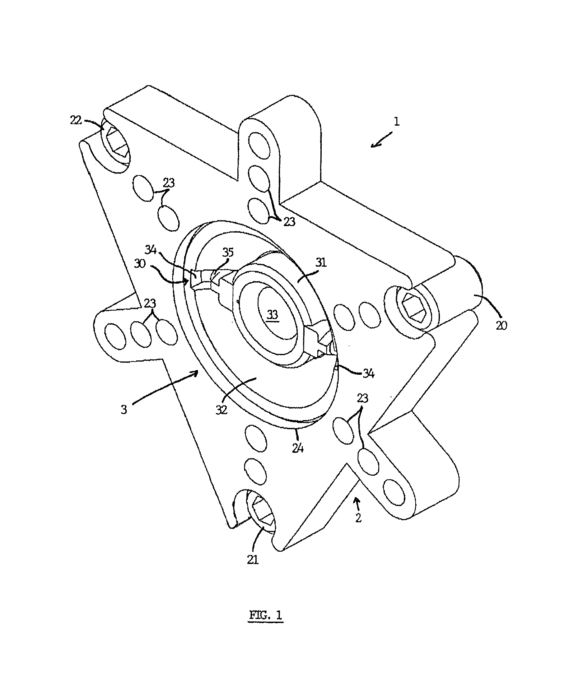
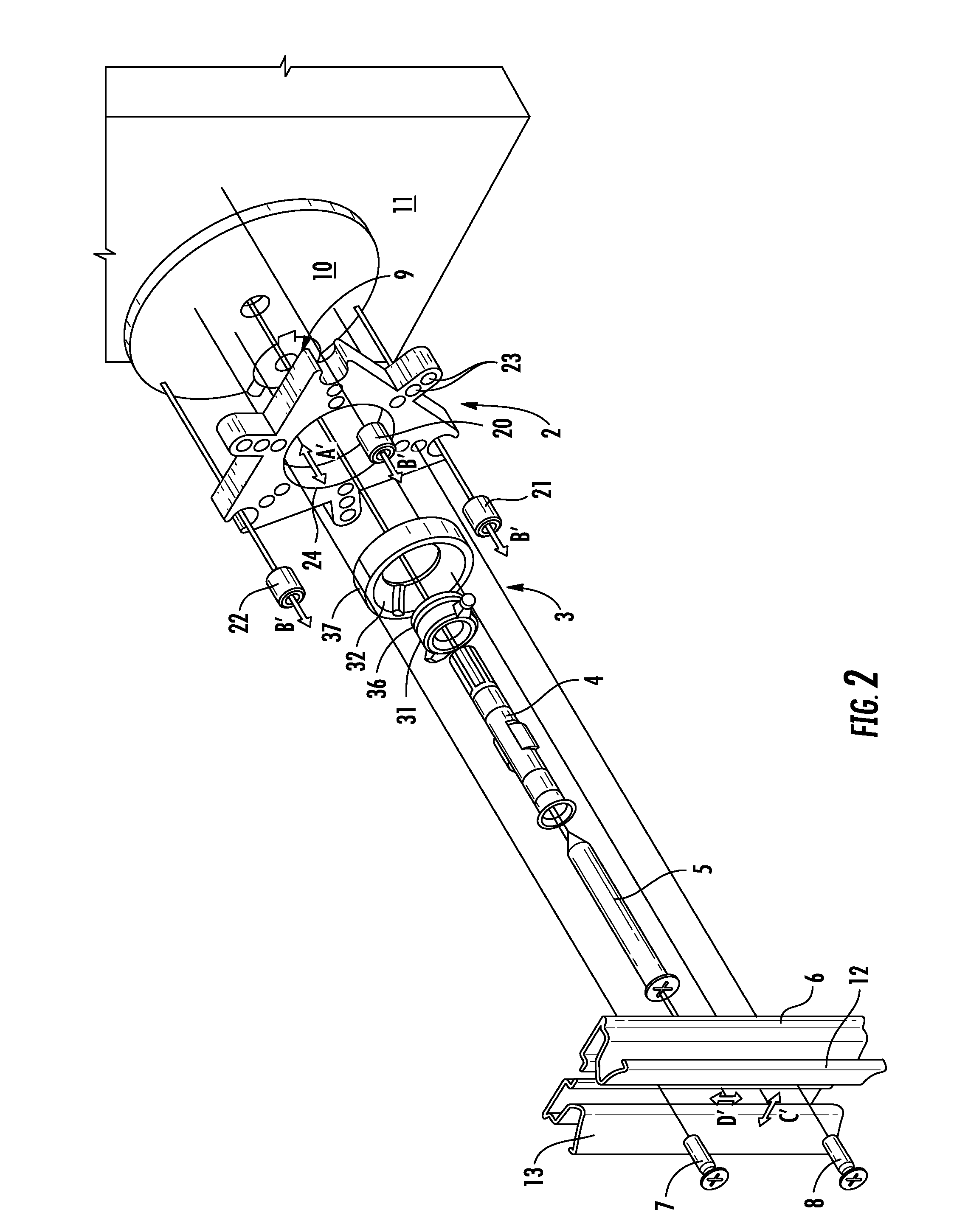
[0028]The mounting assembly 1 shown in FIG. 1 comprises a holder element 2 which is provided for carrying a reveal part 6 of a door / window frame or the like and a fixing element 3 for fixing the assembly 1 at one single location to a reveal wall 11 of a wall opening. The fixing element 3 is provided with a pivot 30, which enables the holder element 2 and the frame part 6 attached thereto to pivot or tilt with respect to the reveal wall 11. Because of this pivot and the single fixing location, the orientation of the holder element 2 can be adjusted to a large extent.

[0029]The fixing element 3 is composed of a number of parts: two concentric elements 31 and 32 which together form the pivot 30, a plug 4 which is inserted through a central opening 33 in the inner concentric element 32 into a hole drilled into the reveal wall 11, and a fixing screw 5 which is screwed into the plug 4 for fixing the whole to the reveal wall 11. The central opening 33 is widened at the front for accommodati...


PUM


Abstract

Mounting assembly for adjustably mounting a frame part, such as for example a reveal part of a door frame or window frame or the like, onto a wall or onto a reveal wall of a wall opening. The mounting assembly comprises a holder element having attachment member on which the frame part can be attached and adjustment member for adjusting the orientation of the holder element with respect to the reveal wall, and a fixing element for fixing the holder element onto the reveal wall. The mounting assembly comprises a single fixing element which is provided for fixing the holder element on a single location to the reveal wall. The fixing element comprises a pivot which enables the holder element to pivot with respect to the reveal wall.

Description

FIELD OF THE INVENTION[0001]The present invention relates to a mounting assembly for adjustably mounting a frame part, such as for example a reveal part of a door frame or window frame or the like, onto a wall or into a wall opening.BACKGROUND OF THE INVENTION[0002]In building constructions it is common that the walls have irregular surfaces, do not extend perpendicular or parallel with respect to each other, the floor, the ceiling etc. Similarly it often happens that the side faces delimiting an opening in a wall, i.e. the reveal walls, have irregular surfaces or are not perfectly perpendicular to the top face of the opening or the floor, or one or more of the adjacent wall faces of the wall in which the opening is located. The wall opening can be any kind of opening in a wall, such as for example a door opening, a window opening, a garage door opening, a gate opening etc. The irregularities can hamper a proper positioning of for example the stiles of a frame in these wall openings...

Claims


Application Information

Patent Timeline
IPC IPC(8): E06B1/04
CPCE06B1/603
Inventor DRIES, RUDI
Owner INDOOR COLLECTION NV
Why Eureka
Try Eureka