
Compressor and method of using compressor

a compressor and compressor technology, applied in the direction of positive displacement liquid engine, pump control, pump parameter, etc., can solve the problems of compressor seizure, and further increase in compressor production cos

Inactive Publication Date: 2010-08-31
TOYOTA BOSHOKU KK +1
View PDF23 Cites 4 Cited by
  • Summary
  • Abstract
  • Description
  • Claims
  • Application Information

AI Technical Summary

Benefits of technology

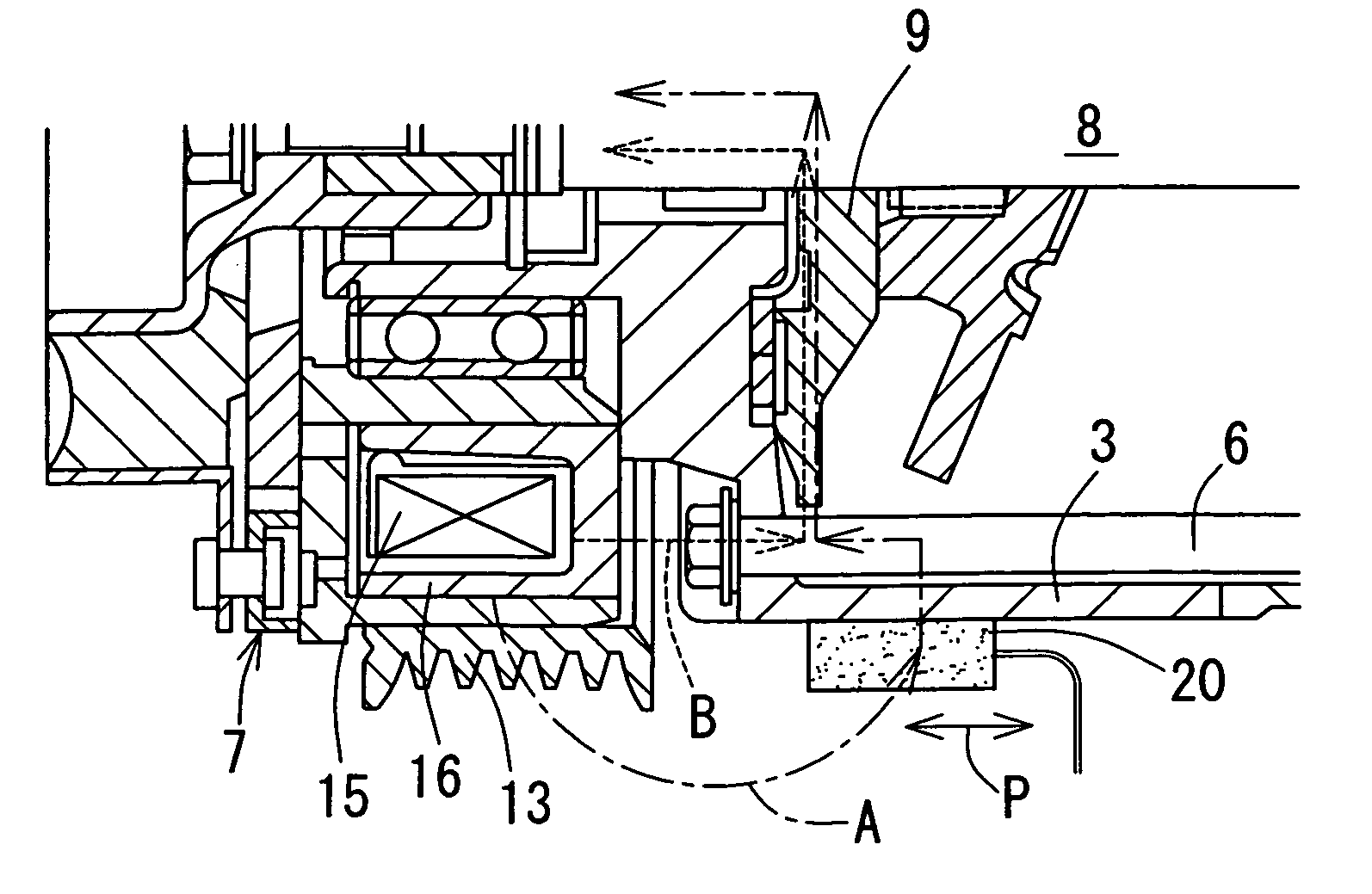
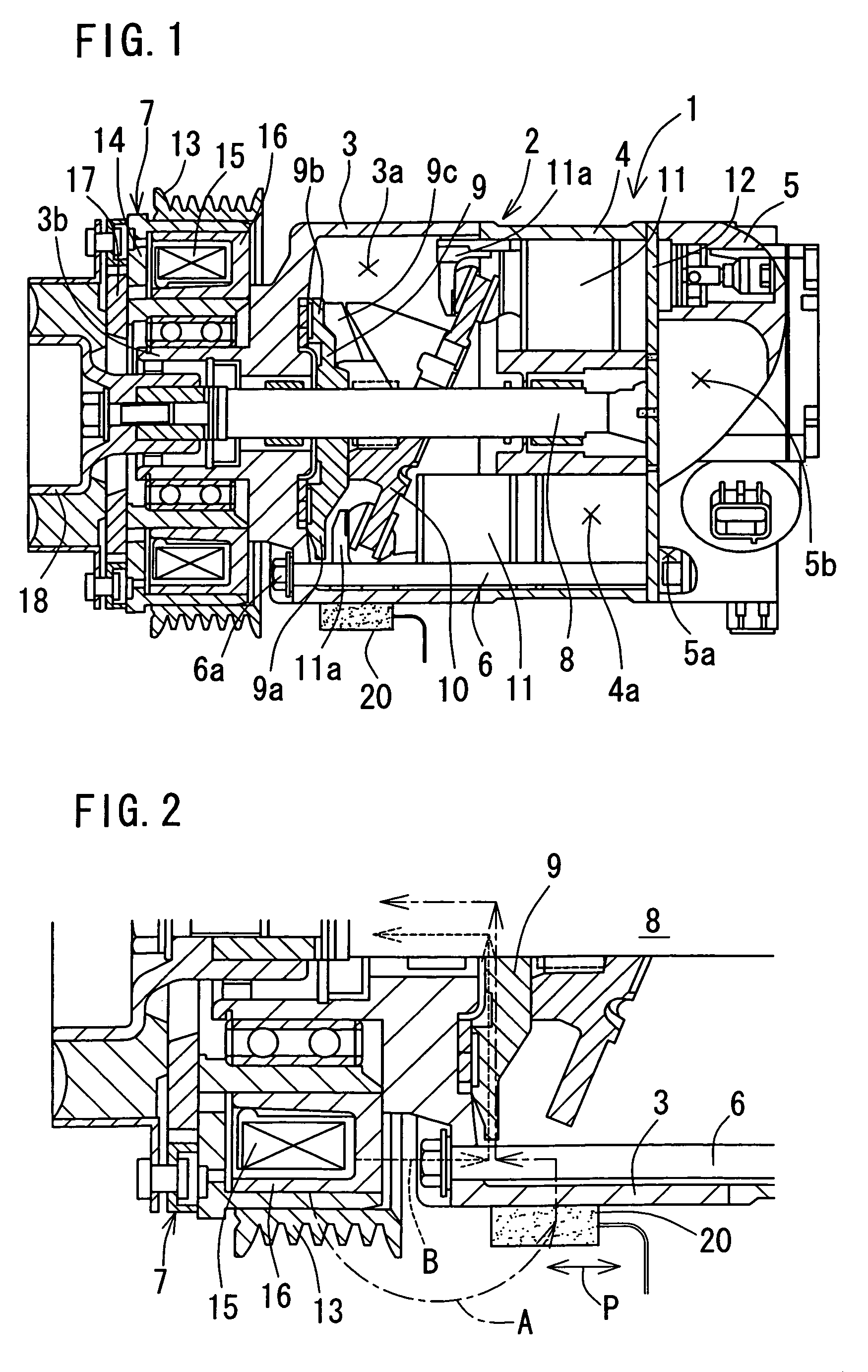
The present invention provides a compressor with a compact and inexpensive structure that does not require drilling the body. The compressor includes a plurality of housing members, a fastener that couples the housing members to one another, an electromagnetic clutch, a drive shaft, a movable member that moves in response to the drive shaft, a detection body, and a magnetic sensor. The detection body and the drive shaft are made of a ferromagnetic material, and the magnetic sensor is a magnetic impedance element. The detection body and the drive shaft are positioned close to each other, and the magnetic sensor is positioned to detect the magnetic flux leaking out from the electromagnetic clutch. The compressor is suitable for air-conditioning of vehicles. The technical effects of the invention include a compact and inexpensive structure, reliable detection of rotational speed, and improved performance and reliability of the compressor.

Problems solved by technology

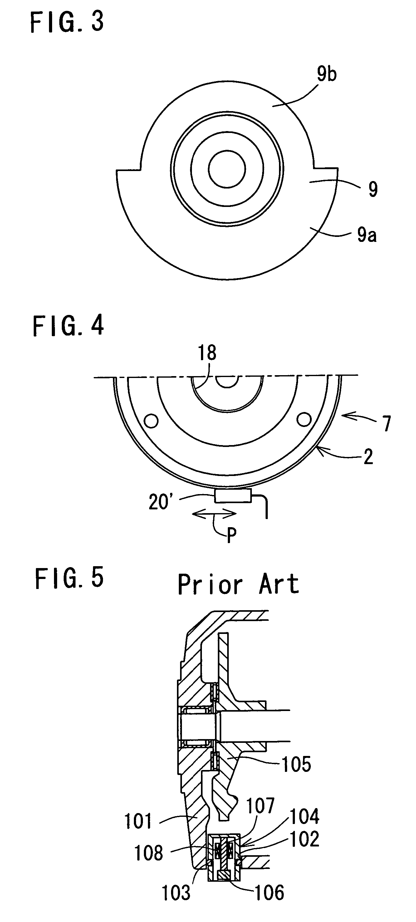
In the above described conventional rotation detecting mechanism, however, the housing member 101 needs to be drilled so as to form the through-hole 102, which leads to an increase in the production cost of the compressor.
Further, a sealing structure employing the O-ring 103 is required, which leads to a further increase in the production cost of the compressor.
In addition, there is a problem, for example, that foreign matters that have adhered to the detection sensor 104 may enter the compressor and cause seizure of the compressor.
This causes a problem that the axial total length of the compressor is increased because of a space for mounting the sensor.
Therefore, this magnetic flux generating source may fall from the detection body and cause seizure or the like of the compressor.
Besides, there is a problem, for example, that the necessity of the magnetic flux generating source entails an increase in the production cost of the compressor.

Method used


Image

  • Compressor and method of using compressor
  • Compressor and method of using compressor
  • Compressor and method of using compressor

Examples


Embodiment Construction

[0053]1. Compressor

[0054]A compressor according to the present invention is provided with the following components, that is, a housing member, a fastener, a drive shaft, a movable member, a detection body, and detection means. This compressor may further be provided with, for example, a swash plate which will be described later.

[0055]The type of compression performed by the compressor may be, for example, reciprocating compression, scroll compression, screw compression, or vane compression.

[0056]The “housing member” is not limited to any specific material, shape, or the like as long as two or more of housing members of the same type can be combined to form a body of the compressor. The number of the housing members to be provided is not limited in particular either. The housing member may be made of, for example, a nonmagnetic material such as aluminum. The housing member may be, for example, a front housing, a cylinder block, a rear housing, and the like.

[0057]The “fastener” is not...


PUM


Abstract

A compressor of the present invention is provided with a plurality of housing members (a front housing, a cylinder block, and a rear housing) that forms a body, a fastener (a bolt member) for coupling the plurality of the housing members to one another, a drive shaft inserted through the body and coupled to a power source via an electromagnetic clutch, a movable member (a piston) that moves in association with the drive shaft to compress a fluid, a detection body that moves in association with the drive shaft, and a detection part for detecting a rotational state of the drive shaft by means of the detection body. A magnetic sensor having a magnetic impedance element constitutes the detection part. The magnetic sensor is provided on an outer lateral face side of the body and in proximity to the fastener.

Description

[0001]The disclosure of Japanese Patent Application No. 2004-372142 filed on Dec. 22, 2004, including the specification, drawings and abstract is incorporated herein by reference in its entirety.BACKGROUND OF THE INVENTION[0002]1. Field of the Invention[0003]The present invention relates to a compressor and a method of using the compressor, and more particularly, to a compressor with a compact and inexpensive structure which does not require drilling a body thereof and a method of using the compressor.[0004]2. Description of the Related Art[0005]A compressor for air-conditioning of a vehicle, which is provided with a rotation detecting mechanism to detect a rotational failure resulting from seizure or the like, has been conventionally known. The rotation detecting mechanism is constructed, for example, by forming a through-hole 102 through a housing member 101 made of a nonmagnetic material and fitting a detection sensor 104 in the through-hole 102 via an O-ring 103 as shown in FIG....

Claims


Application Information

Patent Timeline
Patent Type & Authority Patents(United States)
IPC IPC(8): F04B49/00
CPCF04B27/0895F04B27/1036F04B27/1054F04B27/1081F04B49/103F04B2201/1206
Inventor ONO, MAKOTOSAKUMA, WATARU
Owner TOYOTA BOSHOKU KK
Learn More