
Filter system

Active Publication Date: 2010-08-17
ADVA OPTICAL NETWORKING SE
View PDF16 Cites 14 Cited by
  • Summary
  • Abstract
  • Description
  • Claims
  • Application Information

AI Technical Summary

Benefits of technology

[0011]According to the invention, the filter housing can be inserted through an insertion shaft. In this case, the filter housing can be moved along this shaft by means of a thrust element through which a first thrust may be applied, wherein this motion should take place in a first, usually lateral direction X. In response to the first thrust, the filter housing to be inserted assumes an initial inserted position that, referred to the X-direction, lies relatively close to the desired end position before the displacement in the Y-direction (that is, the second direction) takes place. The insertion shaft is advantageously realized in such a way that the filter housing can be pulled out toward the front, e.g., from underneath the switchgear cabinet, by subjecting it to thrust or tension and reinserted along the same path. The shaft may be arranged underneath the switchgear cabinet or any cable ducts and therefore does not impair the function of the switchgear cabinet.
[0022]The filter system can be advantageously serviced from the front side, namely also in the operative state of the switchgear cabinet. The low structural height furthermore makes it possible to realize a particularly compact and cost-efficient design that can be easily handled.

Problems solved by technology

The insertion and removal of the filter elements has proved quite problematic in practical applications.
In addition, cable ducts frequently extend to the actual switchgear cabinet underneath or laterally thereof such that the insertion of the filter elements, in particular, into the preferred bottom region of the housing is quite complicated and associated with the risk of damaging the switchgear cabinet components.
The disadvantage of this embodiment can be seen in that the arrangement of a filter element requires much space.
The exchange of the filter element is also still a relatively complicated procedure and only possible if direct access to the ventilation channel is provided.
However, the arrangement and the exchange of the filter elements are still quite complicated.
This variation has a complicated constructive design and requires much structural space (particularly for the actuation).

Method used


Image

  • Filter system
  • Filter system
  • Filter system

Examples


Embodiment Construction

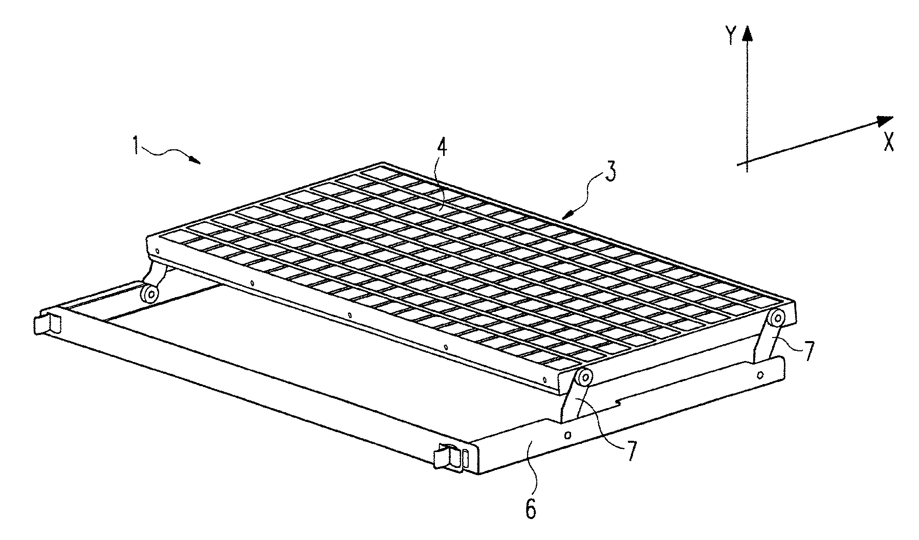
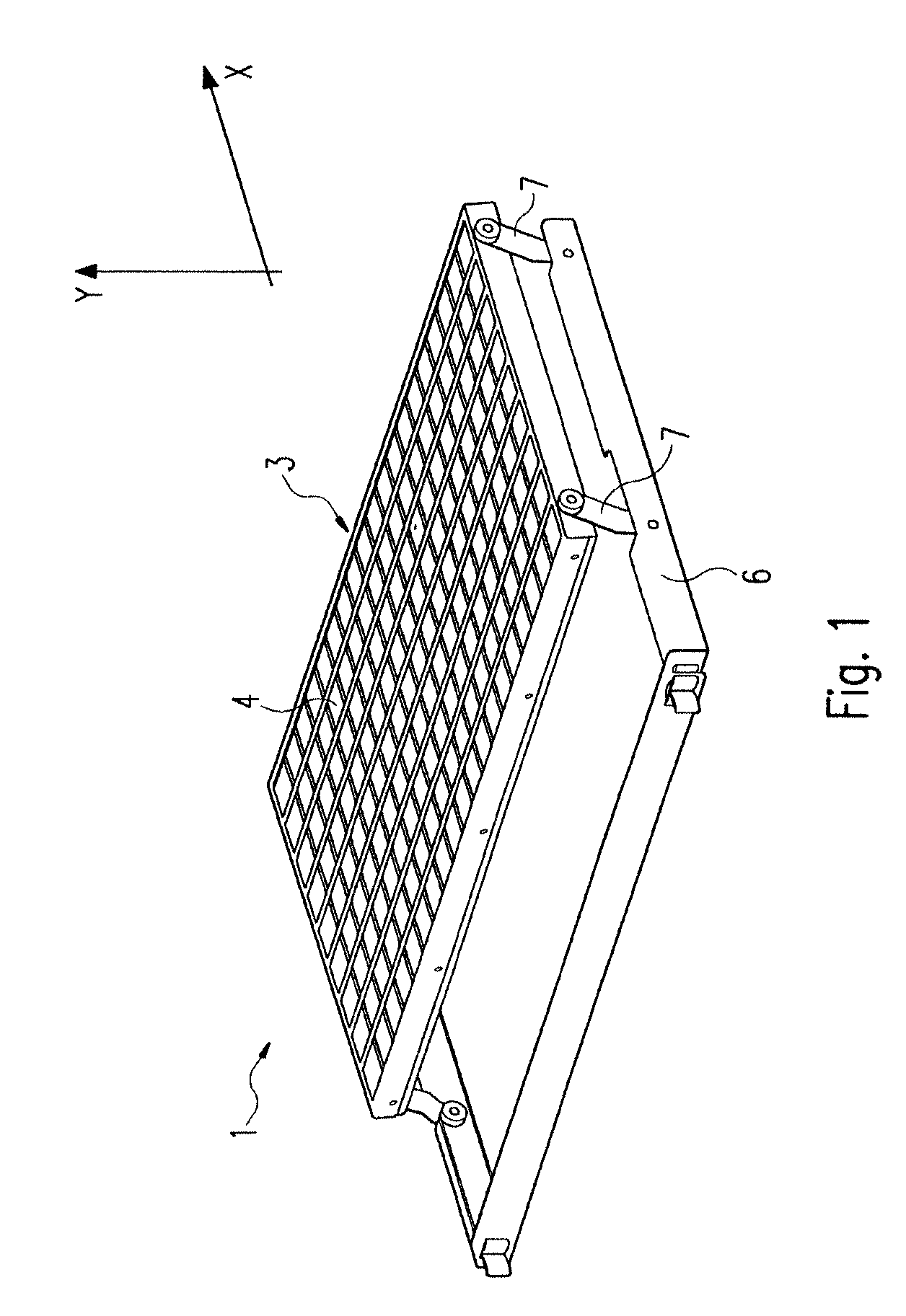
[0027]FIG. 1 shows part of a filter system 1. It comprises a thrust element 6 that can be operated very easily on the front side by means of a cross bar. A filter housing 3 designed for accommodating a filter element 4 is coupled to the thrust element 6 by means of four adjusting bars 7. As indicated in FIG. 1, two adjusting bars 7 are spaced apart at a leading edge of filter housing 3 while the remaining two adjustment bars 7 are space apart at a trailing edge of the filter housing 3. Each adjusting bar 7 is pivotally connected at one end to filter housing 3 and pivotally connected at the opposite end to thrust element 6.

[0028]The filter housing 3 can be pivoted relative to the thrust element 6 during the course of the translatory motion and, in particular, pivoted back into the plane that is essentially defined by the rectangular shape of the thrust elements 6. In this pivoted position, the thrust element 6 can be inserted into the insertion shaft in the X-direction together with ...


PUM

PropertyMeasurementUnit
Shapeaaaaaaaaaa
Distanceaaaaaaaaaa
Displacementaaaaaaaaaa

Abstract

The invention pertains to a filter system, particularly for cleaning the air of a switchgear cabinet to be ventilated, wherein a filter housing can be inserted into an insertion shaft in a first direction and is subjected to a motion perpendicular to the first inserting direction during the course of the inserting motion in order to reach the desired end position of the filter housing.

Description

TECHNICAL FIELD OF THE INVENTION[0001]The present invention pertains to a filter system, particularly for cleaning the air of a switchgear cabinet or subrack carrier to be ventilated, as well as to a switchgear cabinet.BACKGROUND OF THE INVENTION[0002]In switchgear cabinets or subrack carrier housings known from the state of the art, the internal components need to be cooled with air currents. In order to simultaneously prevent soiling of the respective interior, the air is usually cleaned by means of a filter element before it is admitted into the housing.[0003]The insertion and removal of the filter elements has proved quite problematic in practical applications. The filter elements need to be exchangeable and cover a ventilation opening in the switchgear cabinet at a location that is difficult to access. When changing the filter element, it also needs to be taken into account that cables, optical waveguides or other components in the switchgear cabinet or in its immediate vicinit...

Claims


Application Information

Patent Timeline
IPC IPC(8): B01D46/00
CPCB01D46/0005B01D46/008H05K7/20181B01D2265/024Y10S55/31B01D46/88
Inventor FELDMANN, ROLAND
Owner ADVA OPTICAL NETWORKING SE
Learn More