Method, bar blade, and use thereof for milling spiral bevel gears and hypoid gears

a technology of spiral bevel gears and bar blades, which is applied in the direction of gear teeth, gear manufacturing apparatus, manufacturing tools, etc., can solve the problems of reduced wear of individual bar cutting blades and subjected to wear phenomena in the complete profile entering the tooth slot, so as to improve the useful life of cutting blades. the effect of considerable improvemen

Active Publication Date: 2010-08-17
KLINGELNBERG AG
View PDF22 Cites 16 Cited by
  • Summary
  • Abstract
  • Description
  • Claims
  • Application Information

AI Technical Summary

Benefits of technology

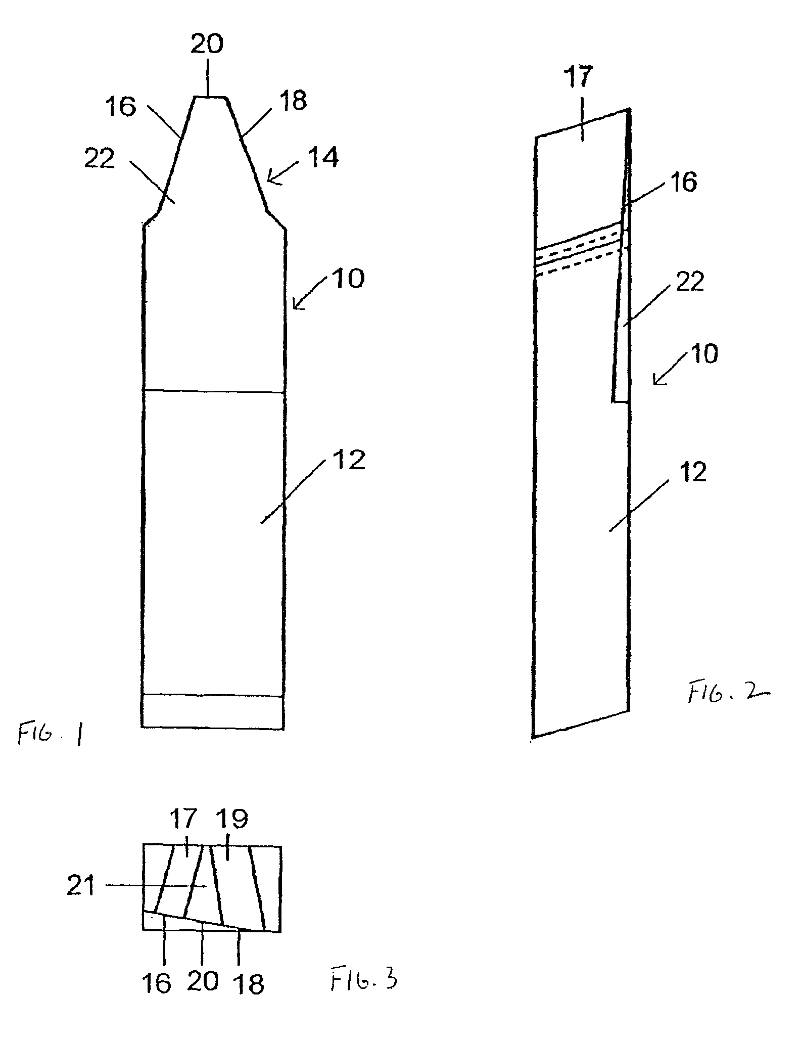
[0018]Furthermore, proceeding from a bar cutting blade of the type initially referred to, this object is accomplished in accordance with the present invention in that the first and the second cutting edge are designed as cutting edges for completely cutting the first and the second tooth flank, respectively, and that the top cutting edge is designed for completely cutting the bottom of the tooth slot, thus enabling the tooth slot to be generated to its complete final geometry using one and the same bar cutting blade in one milling pass.
[0043]When in another embodiment of the bar cutting blade of the invention for form-grinding the bar cutting blade, the rake surface is a rake surface to be reground, a triplex flank ground or profile-sharpened and form-ground bar cutting blade is involved, which affords special advantages. In such a cutting blade the rake surface and the two lateral clearance surfaces are freshly coated upon each regrinding operation. This improves the useful life expectancy of the cutting blades considerably.

Problems solved by technology

Wear of the individual bar cutting blade is diminished, because on each cutting blade the complete profile entering the tooth slot is subjected to wear phenomena.

Method used


Image

  • Method, bar blade, and use thereof for milling spiral bevel gears and hypoid gears
  • Method, bar blade, and use thereof for milling spiral bevel gears and hypoid gears
  • Method, bar blade, and use thereof for milling spiral bevel gears and hypoid gears

Examples


third embodiment

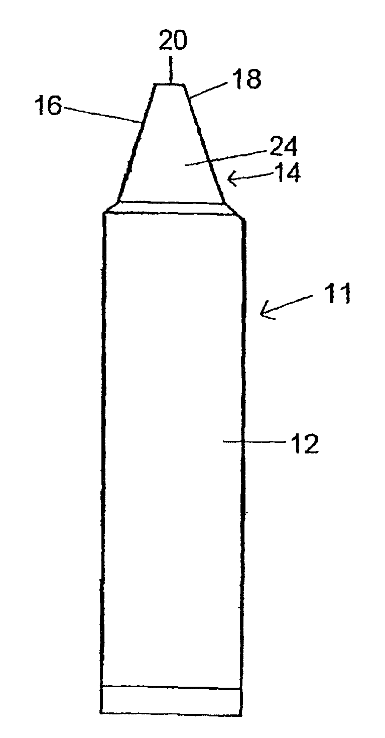
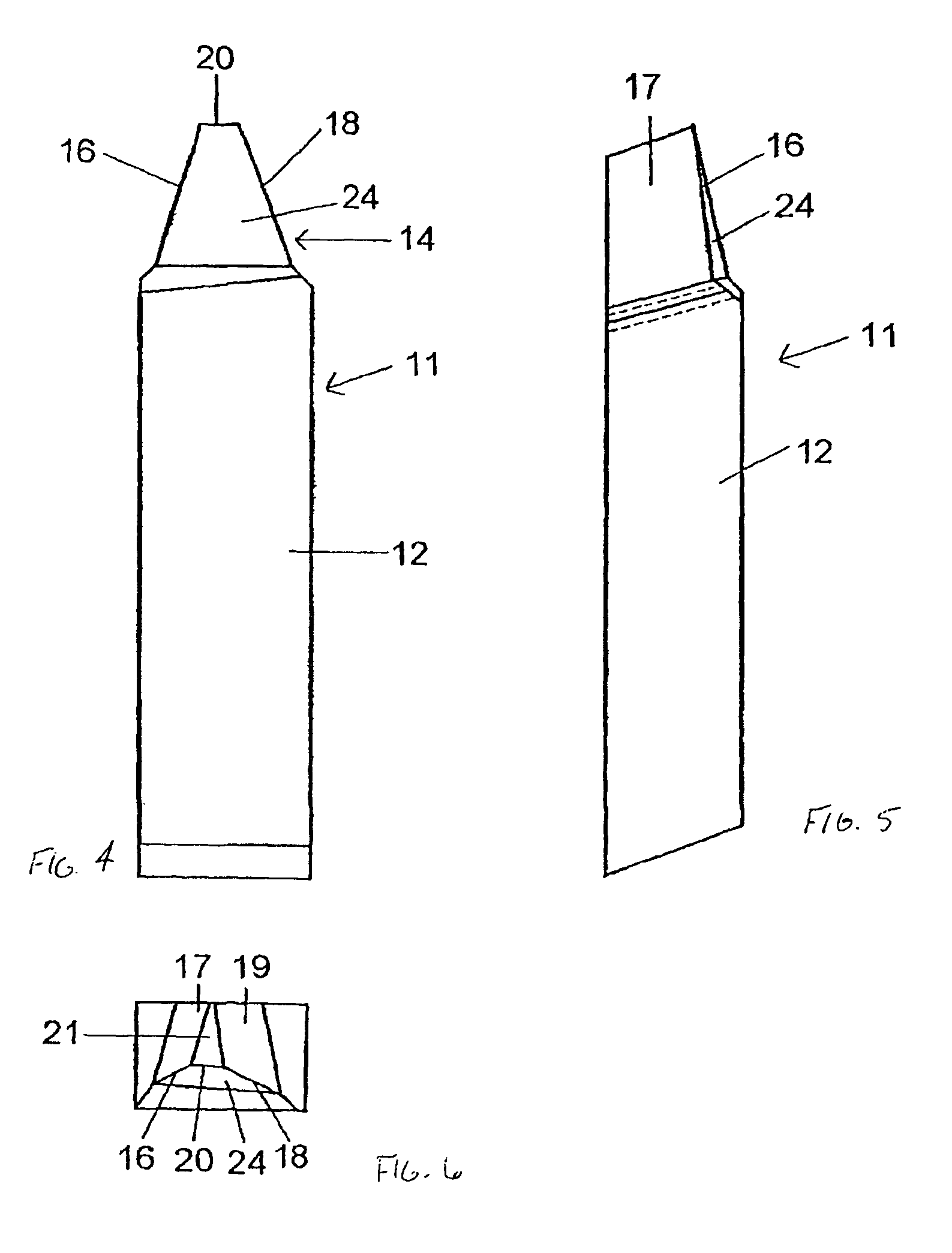
[0063]FIGS. 7 AND 8 show as the bar cutting blade of the invention the triplex flank ground or profile-sharpened and form-ground bar cutting blade 11 with the rake surface 24 to be reground in a front view (FIG. 7) and in a top plan view (FIG. 8). In contrast to the embodiment of FIGS. 4-6 which shows the general case regarding the orientation of the rake surface 24, the embodiment of FIGS. 7 AND 8 relates to the special case in which the rake surface 24 is oriented in such manner that the two cutting edges 16 and 18 are in a symmetrical relationship to each other resulting in like rake angles YS (illustrated in FIG. 11c).

[0064]In the bar cutting blade 11 of FIGS. 7 AND 8 the rake angle YS differs from the rake angle of the bar cutting blade 11 of FIGS. 4-6, being measured according to the representation of FIGS. 11a-f to be discussed in greater detail further below between the rake surface and a reference plane B of the cutting edge (cf., for example, the representation of FIG. 11a...

fourth embodiment

[0065]FIGS. 9 AND 10 show as the bar cutting blade of the invention the triplex flank ground or profile-sharpened and form-ground bar cutting blade 11 with a rake surface 26 to be reground in a front view (FIG. 9) and in a top plan view (FIG. 10). In contrast to the other embodiments, the rake surface 26 between the first and second cutting edges 16, 18 is curved in a concave configuration. In this case both cutting edges 16, 18 result in a positive rake angle.

[0066]FIGS. 11a-f show the size and the position of the rake angles YS for different embodiments of the bar cutting blade of the invention, i.e., in FIG. 11a for the bar cutting blade 10 of FIGS. 1-3, in FIG. 11b for the bar cutting blade 11 of FIGS. 4-6, in FIG. 11c for the bar cutting blade 11 of FIGS. 7 and 8, in FIG. 11d for the bar cutting blade 11 which, while corresponding to FIGS. 4-6, has its rake surface 24 angled in inverted position relative to the reference plane B, in FIG. 11e for the bar cutting blade 11 of FIGS...


PUM

PropertyMeasurementUnit
rake anglesaaaaaaaaaa
rake angleaaaaaaaaaa

Abstract

In a method and a bar blade for milling spiral bevel gears and hypoid gears, a shaft of the bar blade has a blade profile that is formed by the cross-section of at least one cutting area, at least two free areas, and at least one top area. The blade profile is provided with a first cutting edge for a first flank, a second cutting edge for a second flank that faces the first flank, and a top cutting edge for the bottom of a tooth space. The first and the second cutting edge are embodied as principal cutting edges for completely cutting the first or second flank. The top cutting edge is configured for completely cutting the bottom of the tooth space such that the tooth space comprising the complete final geometry is created in one milling process by means of one and the same bar blade.

Description

FIELD OF THE INVENTION[0001]This invention relates to a method for milling spiral bevel gears and hypoid gears using profile-sharpened or profile-sharpened and additionally form-ground bar cutting blades each having a shank and at one end of the shank a cutting edge profile which, for producing a tooth slot, enables a first tooth flank, at least a portion of the bottom of the tooth slot, and least a portion of a second tooth flank lying opposite said first tooth flank to be cut.[0002]Furthermore, the present invention relates to a profile-sharpened or profile-sharpened and additionally form-ground bar cutting blade for milling spiral bevel gears and hypoid gears, with a shank and with a cutting edge profile formed at one end of the shank by the intersection of at least one rake surface, at least two clearance surfaces and at least one top surface, said cutting edge profile including, for producing a tooth slot, a first cutting edge for a first tooth flank, a second cutting edge for ...

Claims


Application Information

Patent Timeline
Patent Type & Authority Patents(United States)
IPC IPC(8): B26D1/12B23F5/20B23F21/22
CPCB23F21/226Y10T29/49476Y10T407/1705Y10T29/5176Y10T409/108586Y10T409/103816Y10T409/104134Y10T409/103975B23F9/10B23P15/38B23C2220/56B23C2220/605
Inventor RIBBECK, KARL MARTIN
Owner KLINGELNBERG AG
Why Eureka
Try Eureka